ST62T25CB6 STMicroelectronics, ST62T25CB6 Datasheet - Page 60
ST62T25CB6
Manufacturer Part Number
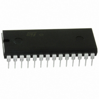
ST62T25CB6
Description
IC MCU 8BIT OTP 4K 28 PDIP
Manufacturer
STMicroelectronics
Series
ST6r
Specifications of ST62T25CB6
Core Processor
ST6
Core Size
8-Bit
Speed
8MHz
Peripherals
LVD, POR, WDT
Number Of I /o
20
Program Memory Size
4KB (4K x 8)
Program Memory Type
OTP
Ram Size
64 x 8
Voltage - Supply (vcc/vdd)
3 V ~ 6 V
Data Converters
A/D 16x8b
Oscillator Type
Internal
Operating Temperature
-40°C ~ 85°C
Package / Case
28-DIP (0.600", 15.24mm)
Processor Series
ST62T2x
Core
ST6
Data Bus Width
8 bit
Data Ram Size
64 B
Maximum Clock Frequency
8 MHz
Number Of Programmable I/os
20
Number Of Timers
1
Operating Supply Voltage
3 V to 6 V
Maximum Operating Temperature
+ 85 C
Mounting Style
Through Hole
Development Tools By Supplier
ST62GP-EMU2, ST62E2XC-EPB/110, ST62E6XC-EPB/US, ST622XC-KIT/110, STREALIZER-II
Minimum Operating Temperature
- 40 C
On-chip Adc
16-ch x 8-bit
Lead Free Status / RoHS Status
Lead free / RoHS Compliant
Eeprom Size
-
Connectivity
-
Lead Free Status / Rohs Status
Lead free / RoHS Compliant
Other names
497-2100-5
Available stocks
Company
Part Number
Manufacturer
Quantity
Price
Company:

Part Number:
ST62T25CB6
Manufacturer:
ST
Quantity:
310
Company:
Part Number:
ST62T25CB6
Manufacturer:
STMicroelectronics
Quantity:
5


ST6215CM-Auto ST6225CM-Auto
INSTRUCTION SET (Cont’d)
Conditional Branch. Branch instructions perform
a branch in the program when the selected condi-
tion is met.
Bit Manipulation Instructions. These instruc-
tions can handle any bit in Data space memory.
One group either sets or clears. The other group
(see Conditional Branch) performs the bit test
branch operations.
Table 18. Conditional Branch Instructions
Notes
b
e
ee
Table 19. Bit Manipulation Instructions
Notes:
b
rr
Bit Manipulation Instructions should not be used on Port Data Registers and any registers with read only and/or write only bits (see I/O port
chapter)
Table 20. Control Instructions
Notes:
1.
Table 21. Jump & Call Instructions
Notes:
abc 12-bit address
*
60/100
1
JRC e
JRNC e
JRZ e
JRNZ e
JRR b, rr, ee
JRS b, rr, ee
SET b,rr
RES b,rr
NOP
RET
RETI
STOP
WAIT
CALL abc
JP abc
3-bit address
5 bit signed displacement in the range -15 to +16
8 bit signed displacement in the range -126 to +129
3-bit address
Data space register
This instruction is deactivated and a WAIT is automatically executed instead of a STOP if the watchdog function is selected.
Affected
Not Affected
Instruction
Instruction
Instruction
Instruction
:
(1)
C = 1
C = 0
Z = 1
Z = 0
Bit = 0
Bit = 1
Bit Direct
Bit Direct
Inherent
Inherent
Inherent
Inherent
Inherent
Extended
Extended
Addressing Mode
Addressing Mode
Addressing Mode
Branch If
Bytes
Bytes
Bytes
Bytes
2
2
1
1
1
1
3
3
2
2
1
1
1
1
1
rr
*
Control Instructions. Control instructions control
microcontroller operations during program execu-
tion.
Jump and Call. These two instructions are used
to perform long (12-bit) jumps or subroutine calls
to any location in the whole program space.
*
*Not Affected
Affected. The tested bit is shifted into carry.
Not Affected
Data space register
Cycles
Cycles
Cycles
Cycles
Not Affected
4
4
2
2
2
2
5
5
4
4
2
2
2
2
2
Z
Z
Z
Z
*
*
*
*
*
*
*
*
*
*
*
*
*
*
Flags
Flags
Flags
Flags
C
C
C
C
*
*
*
*
*
*
*
*
*
*
*
*
Related parts for ST62T25CB6
Image
Part Number
Description
Manufacturer
Datasheet
Request
R

Part Number:
Description:
STMicroelectronics [RIPPLE-CARRY BINARY COUNTER/DIVIDERS]
Manufacturer:
STMicroelectronics
Datasheet:
Part Number:
Description:
STMicroelectronics [LIQUID-CRYSTAL DISPLAY DRIVERS]
Manufacturer:
STMicroelectronics
Datasheet:

Part Number:
Description:
BOARD EVAL FOR MEMS SENSORS
Manufacturer:
STMicroelectronics
Datasheet:
Part Number:
Description:
NPN TRANSISTOR POWER MODULE
Manufacturer:
STMicroelectronics
Datasheet:
Part Number:
Description:
TURBOSWITCH ULTRA-FAST HIGH VOLTAGE DIODE
Manufacturer:
STMicroelectronics
Datasheet:
Part Number:
Description:
Manufacturer:
STMicroelectronics
Datasheet:
Part Number:
Description:
DIODE / SCR MODULE
Manufacturer:
STMicroelectronics
Datasheet:
Part Number:
Description:
DIODE / SCR MODULE
Manufacturer:
STMicroelectronics
Datasheet:
Part Number:
Description:
Search -----> STE16N100
Manufacturer:
STMicroelectronics
Datasheet:
Part Number:
Description:
Search ---> STE53NA50
Manufacturer:
STMicroelectronics
Datasheet:
Part Number:
Description:
NPN Transistor Power Module
Manufacturer:
STMicroelectronics
Datasheet:
Part Number:
Description:
DIODE / SCR MODULE
Manufacturer:
STMicroelectronics
Datasheet: