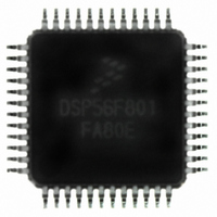
DSP56F801FA80E Freescale Semiconductor, DSP56F801FA80E Datasheet - Page 25

DSP56F801FA80E
Manufacturer Part Number
DSP56F801FA80E
Description
IC DSP 80MHZ 8K FLASH 48-LQFP
Manufacturer
Freescale Semiconductor
Series
56F8xxr
Datasheet
1.DSP56F801EVM.pdf
(48 pages)
Specifications of DSP56F801FA80E
Core Processor
56800
Core Size
16-Bit
Speed
80MHz
Connectivity
SCI, SPI
Peripherals
POR, PWM, WDT
Number Of I /o
11
Program Memory Size
20KB (10K x 16)
Program Memory Type
FLASH
Ram Size
2K x 16
Voltage - Supply (vcc/vdd)
3 V ~ 3.6 V
Data Converters
A/D 8x12b
Oscillator Type
Internal
Operating Temperature
-40°C ~ 85°C
Package / Case
48-LQFP
Package
48LQFP
Family Name
56F8xx
Maximum Speed
80 MHz
Operating Supply Voltage
3.3 V
Data Bus Width
16 Bit
Number Of Programmable I/os
11
Interface Type
SCI/SPI
On-chip Adc
2(4-chx12-bit)
Number Of Timers
1
Lead Free Status / RoHS Status
Lead free / RoHS Compliant
Eeprom Size
-
Available stocks
Company
Part Number
Manufacturer
Quantity
Price
Company:
Part Number:
DSP56F801FA80E
Manufacturer:
Freescale Semiconductor
Quantity:
10 000
Part Number:
DSP56F801FA80E
Manufacturer:
FREESCALE
Quantity:
20 000
3.5.3
The recommended method of connecting an external clock is given in
source is connected to XTAL and the EXTAL pin is grounded.
3.5.4
An internal relaxation oscillator can supply the reference frequency when an external frequency source or
crystal are not used. During a 56F801 boot or reset sequence, the relaxation oscillator is enabled by default,
and the PRECS bit in the PLLCR word is set to 0
relaxation oscillator can be deselected instead by setting the PRECS bit in the PLLCR to 1. When this
occurs, the PRECSS bit in the PLLSR (prescaler clock select status register) data word also sets to 1. If a
changeover between internal and external oscillators is required at startup, internal device circuits
Freescale Semiconductor
Frequency of operation (external clock driver)
Clock Pulse Width
1. See
2. May not exceed 60MHz for the DSP56F801FA60 device.
3. The high or low pulse width must be no smaller than 6.25ns or the chip will not function. However, the high pulse width
does not have to be any particular percent of the low pulse width.
4. Parameters listed are guaranteed by design.
External
Note: The midpoint is V
Clock
External Clock Source
Use of On-Chip Relaxation Oscillator
Figure 3-9
Operating Conditions:
Table 3-8 External Clock Operation Timing Requirements
Characteristic
3, 4
for details on using the recommended connection of an external clock driver.
10%
50%
90%
Figure 3-9 Connecting an External Clock Signal
t
PW
IL
+ (V
Figure 3-10 External Clock Timing
IH
– V
IL
V
56F801 Technical Data, Rev. 17
)/2.
SS
External Clock
= V
t
1
PW
SSA
XTAL
= 0 V, V
56F801
Symbol
(Section
f
t
osc
PW
EXTAL
DD
V
= V
SS
3.5). If an external oscillator is connected, the
DDA
6.25
Min
0
= 3.0–3.6 V, T
Typ
Figure
—
—
A
= –40° to +85°C
3-9. The external clock
Max
80
—
3
2
External Clock Operation
10%
50%
90%
MHz
V
V
Unit
ns
IH
IL
25


