MC908GP32CPE Freescale Semiconductor, MC908GP32CPE Datasheet - Page 65
MC908GP32CPE
Manufacturer Part Number
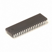
MC908GP32CPE
Description
IC MCU 8MHZ 32K FLASH 40-DIP
Manufacturer
Freescale Semiconductor
Series
HC08r
Datasheet
1.MC908GP32CFBE.pdf
(266 pages)
Specifications of MC908GP32CPE
Core Processor
HC08
Core Size
8-Bit
Speed
8MHz
Connectivity
SCI, SPI
Peripherals
LVD, POR, PWM
Number Of I /o
33
Program Memory Size
32KB (32K x 8)
Program Memory Type
FLASH
Ram Size
512 x 8
Voltage - Supply (vcc/vdd)
2.7 V ~ 5.5 V
Data Converters
A/D 8x8b
Oscillator Type
Internal
Operating Temperature
-40°C ~ 85°C
Package / Case
40-DIP (0.600", 15.24mm)
Processor Series
HC08GP
Core
HC08
Data Bus Width
8 bit
Data Ram Size
512 B
Interface Type
SCI, SPI
Maximum Clock Frequency
8 MHz
Number Of Programmable I/os
33
Number Of Timers
4
Maximum Operating Temperature
+ 85 C
Mounting Style
Through Hole
Development Tools By Supplier
FSICEBASE, DEMO908GZ60E, M68CBL05CE, M68EML08GPGTE
Minimum Operating Temperature
- 40 C
On-chip Adc
8 bit, 8 Channel
Lead Free Status / RoHS Status
Lead free / RoHS Compliant
Eeprom Size
-
Lead Free Status / Rohs Status
Details
Available stocks
Company
Part Number
Manufacturer
Quantity
Price
Company:

Part Number:
MC908GP32CPE
Manufacturer:
NXP
Quantity:
9 282
Part Number:
MC908GP32CPE
Manufacturer:
FREESCALE
Quantity:
20 000


The PLL also may operate in manual mode (AUTO = 0). Manual mode is used by systems that do not
require an indicator of the lock condition for proper operation. Such systems typically operate well below
f
The following conditions apply when in manual mode:
5.3.6 Programming the PLL
The following procedure shows how to program the PLL.
Freescale Semiconductor
BUSMAX
1. Choose the desired bus frequency, f
2. Calculate the desired VCO frequency (four times the desired bus frequency).
3. Choose a practical PLL (crystal) reference frequency, f
•
•
•
•
•
•
•
The LOCK bit is set when the VCO frequency is within a certain tolerance and is cleared when the
VCO frequency is out of a certain tolerance. (See
more information.)
CPU interrupts can occur if enabled (PLLIE = 1) when the PLL’s lock condition changes, toggling
the LOCK bit. (See
ACQ is a writable control bit that controls the mode of the filter. Before turning on the PLL in manual
mode, the ACQ bit must be clear.
Before entering tracking mode (ACQ = 1), software must wait a given time, t
Acquisition/Lock Time
control register (PCTL).
Software must wait a given time, t
clock source to CGMOUT (BCS = 1).
The LOCK bit is disabled.
CPU interrupts from the CGM are disabled.
Typically, the reference crystal is 32.768 kHz and R = 1.
Frequency errors to the PLL are corrected at a rate of f
this rate must be as fast as possible. The VCO frequency must be an integer multiple of this rate.
The relationship between the VCO frequency, f
P, the power of two multiplier, and N, the range multiplier, are integers.
In cases where desired bus frequency has some tolerance, choose f
either by other module requirements (such as modules which are clocked by CGMXCLK), cost
requirements, or ideally, as high as the specified range allows. See
Specifications. Choose the reference divider, R = 1. After choosing N and P, the actual bus
frequency can be determined using equation in 2 above.
.
The round function in the following equations means that the real number
should be rounded to the nearest integer number.
5.5.1 PLL Control
Specifications.), after turning on the PLL by setting PLLON in the PLL
MC68HC908GP32 Data Sheet, Rev. 10
f
AL
VCLKDES
f
VCLK
, after entering tracking mode before selecting the PLL as the
BUSDES
Register.)
=
NOTE
=
2
----------- - f
.
P
R
4 f
N
×
VCLK
(
BUSDES
RCLK
5.8 Acquisition/Lock Time Specifications
, and the reference frequency, f
RCLK
RCLK
)
/R. For stability and lock time reduction,
, and the reference clock divider, R.
Chapter 19 Electrical
RCLK
to a value determined
ACQ
Functional Description
(See
RCLK
5.8
, is
for
65
Related parts for MC908GP32CPE
Image
Part Number
Description
Manufacturer
Datasheet
Request
R

Part Number:
Description:
Manufacturer:
Freescale Semiconductor, Inc
Datasheet:
Part Number:
Description:
Manufacturer:
Freescale Semiconductor, Inc
Datasheet:
Part Number:
Description:
Manufacturer:
Freescale Semiconductor, Inc
Datasheet:
Part Number:
Description:
Manufacturer:
Freescale Semiconductor, Inc
Datasheet:
Part Number:
Description:
Manufacturer:
Freescale Semiconductor, Inc
Datasheet:
Part Number:
Description:
Manufacturer:
Freescale Semiconductor, Inc
Datasheet:
Part Number:
Description:
Manufacturer:
Freescale Semiconductor, Inc
Datasheet:
Part Number:
Description:
Manufacturer:
Freescale Semiconductor, Inc
Datasheet:
Part Number:
Description:
Manufacturer:
Freescale Semiconductor, Inc
Datasheet:
Part Number:
Description:
Manufacturer:
Freescale Semiconductor, Inc
Datasheet:
Part Number:
Description:
Manufacturer:
Freescale Semiconductor, Inc
Datasheet:
Part Number:
Description:
Manufacturer:
Freescale Semiconductor, Inc
Datasheet:
Part Number:
Description:
Manufacturer:
Freescale Semiconductor, Inc
Datasheet:
Part Number:
Description:
Manufacturer:
Freescale Semiconductor, Inc
Datasheet:
Part Number:
Description:
Manufacturer:
Freescale Semiconductor, Inc
Datasheet: