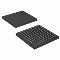
ATSAM3U2EA-CU Atmel, ATSAM3U2EA-CU Datasheet - Page 89

ATSAM3U2EA-CU
Manufacturer Part Number
ATSAM3U2EA-CU
Description
IC MCU 32BIT 128KB FLSH 144LFBGA
Manufacturer
Atmel
Series
SAM3Ur
Specifications of ATSAM3U2EA-CU
Core Processor
ARM® Cortex-M3™
Core Size
32-Bit
Speed
96MHz
Connectivity
EBI/EMI, I²C, MMC, SPI, SSC, UART/USART, USB
Peripherals
Brown-out Detect/Reset, DMA, I²S, POR, PWM, WDT
Number Of I /o
96
Program Memory Size
128KB (128K x 8)
Program Memory Type
FLASH
Ram Size
36K x 8
Voltage - Supply (vcc/vdd)
1.65 V ~ 1.95 V
Data Converters
A/D 8x10b, 8x12b
Oscillator Type
Internal
Operating Temperature
-40°C ~ 85°C
Package / Case
144-LFBGA
Processor Series
ATSAM3x
Core
ARM Cortex M3
Data Bus Width
32 bit
Data Ram Size
36 KB
Interface Type
4xUSART, 2xTWI, 5xSPI, Bus
Maximum Clock Frequency
96 MHz
Number Of Programmable I/os
96
Number Of Timers
8
Operating Supply Voltage
1.62 V to 3.6 V
Maximum Operating Temperature
+ 85 C
Mounting Style
SMD/SMT
3rd Party Development Tools
JTRACE-CM3, MDK-ARM, RL-ARM, ULINK2
Development Tools By Supplier
ATSAM3U-EK
Minimum Operating Temperature
- 40 C
Lead Free Status / RoHS Status
Lead free / RoHS Compliant
Eeprom Size
-
Lead Free Status / Rohs Status
Details
Available stocks
Company
Part Number
Manufacturer
Quantity
Price
- Current page: 89 of 1171
- Download datasheet (25Mb)
13.7
13.7.1
13.7.1.1
13.7.1.2
13.7.1.3
13.7.2
13.7.2.1
6430D–ATARM–25-Mar-11
Power management
Entering sleep mode
Wakeup from sleep mode
Wait for interrupt
Wait for event
Sleep-on-exit
Wakeup from WFI or sleep-on-exit
The Cortex-M3 processor sleep modes reduce power consumption:
The SLEEPDEEP bit of the SCR selects which sleep mode is used, see
ter” on page
Modes” in the PMC section of the datasheet.
This section describes the mechanisms for entering sleep mode, and the conditions for waking
up from sleep mode.
This section describes the mechanisms software can use to put the processor into sleep mode.
The system can generate spurious wakeup events, for example a debug operation wakes up the
processor. Therefore software must be able to put the processor back into sleep mode after
such an event. A program might have an idle loop to put the processor back to sleep mode.
The wait for interrupt instruction, WFI, causes immediate entry to sleep mode. When the proces-
sor executes a WFI instruction it stops executing instructions and enters sleep mode. See
on page 165
The wait for event instruction, WFE, causes entry to sleep mode conditional on the value of an
one-bit event register. When the processor executes a WFE instruction, it checks this register:
See
If the SLEEPONEXIT bit of the SCR is set to 1, when the processor completes the execution of
an exception handler it returns to Thread mode and immediately enters sleep mode. Use this
mechanism in applications that only require the processor to run when an exception occurs.
The conditions for the processor to wakeup depend on the mechanism that cause it to enter
sleep mode.
Normally, the processor wakes up only when it detects an exception with sufficient priority to
cause exception entry.
Some embedded systems might have to execute system restore tasks after the processor
wakes up, and before it executes an interrupt handler. To achieve this set the PRIMASK bit to 1
and the FAULTMASK bit to 0. If an interrupt arrives that is enabled and has a higher priority than
current exception priority, the processor wakes up but does not execute the interrupt handler
• Backup Mode
• Wait Mode
• Sleep Mode
• if the register is 0 the processor stops executing instructions and enters sleep mode
• if the register is 1 the processor clears the register to 0 and continues executing instructions
without entering sleep mode.
“WFE” on page 164
189. For more information about the behavior of the sleep modes see “Low Power
for more information.
for more information.
SAM3U Series
“System Control Regis-
“WFI”
89
Related parts for ATSAM3U2EA-CU
Image
Part Number
Description
Manufacturer
Datasheet
Request
R

Part Number:
Description:
KIT EVAL FOR AT91SAM3U CORTEX
Manufacturer:
Atmel
Datasheet:

Part Number:
Description:
AT91 ARM Thumb-based Microcontrollers
Manufacturer:
ATMEL [ATMEL Corporation]
Datasheet:

Part Number:
Description:
DEV KIT FOR AVR/AVR32
Manufacturer:
Atmel
Datasheet:

Part Number:
Description:
INTERVAL AND WIPE/WASH WIPER CONTROL IC WITH DELAY
Manufacturer:
ATMEL Corporation
Datasheet:

Part Number:
Description:
Low-Voltage Voice-Switched IC for Hands-Free Operation
Manufacturer:
ATMEL Corporation
Datasheet:

Part Number:
Description:
MONOLITHIC INTEGRATED FEATUREPHONE CIRCUIT
Manufacturer:
ATMEL Corporation
Datasheet:

Part Number:
Description:
AM-FM Receiver IC U4255BM-M
Manufacturer:
ATMEL Corporation
Datasheet:

Part Number:
Description:
Monolithic Integrated Feature Phone Circuit
Manufacturer:
ATMEL Corporation
Datasheet:

Part Number:
Description:
Multistandard Video-IF and Quasi Parallel Sound Processing
Manufacturer:
ATMEL Corporation
Datasheet:

Part Number:
Description:
High-performance EE PLD
Manufacturer:
ATMEL Corporation
Datasheet:

Part Number:
Description:
8-bit Flash Microcontroller
Manufacturer:
ATMEL Corporation
Datasheet:

Part Number:
Description:
2-Wire Serial EEPROM
Manufacturer:
ATMEL Corporation
Datasheet:


