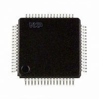
P89LPC9408FBD,557 NXP Semiconductors, P89LPC9408FBD,557 Datasheet - Page 41

P89LPC9408FBD,557
Manufacturer Part Number
P89LPC9408FBD,557
Description
IC 80C51 MCU FLASH 8K 64-LQFP
Manufacturer
NXP Semiconductors
Series
LPC900r
Datasheet
1.P89LPC9408FBD557.pdf
(69 pages)
Specifications of P89LPC9408FBD,557
Program Memory Type
FLASH
Program Memory Size
8KB (8K x 8)
Package / Case
64-LQFP
Core Processor
8051
Core Size
8-Bit
Speed
18MHz
Connectivity
I²C, SPI, UART/USART
Peripherals
Brown-out Detect/Reset, LCD, LED, POR, PWM, WDT
Number Of I /o
23
Eeprom Size
512 x 8
Ram Size
256 x 8
Voltage - Supply (vcc/vdd)
2.4 V ~ 3.6 V
Data Converters
A/D 8x10b
Oscillator Type
Internal
Operating Temperature
-40°C ~ 85°C
Processor Series
P89LPC9x
Core
80C51
Data Bus Width
8 bit
Data Ram Size
256 B
Interface Type
I2C/SPI/UART
Maximum Clock Frequency
18 MHz
Number Of Programmable I/os
23
Number Of Timers
2
Operating Supply Voltage
2.4 V to 3.6 V
Maximum Operating Temperature
+ 85 C
Mounting Style
SMD/SMT
3rd Party Development Tools
PK51, CA51, A51, ULINK2
Minimum Operating Temperature
- 40 C
On-chip Adc
8-ch x 10-bit
Lead Free Status / RoHS Status
Lead free / RoHS Compliant
For Use With
OM10097 - KIT FOR LCD DEMO LPC9408EPM900K - EMULATOR/PROGRAMMER NXP P89LPC9568-4000 - DEMO BOARD SPI/I2C TO DUAL UART568-3510 - DEMO BOARD SPI/I2C TO UART568-1759 - EMULATOR DEBUGGER/PROGRMMR LPC9X
Lead Free Status / Rohs Status
Lead free / RoHS Compliant
Other names
568-3228
935280583557
P89LPC9408FBD
935280583557
P89LPC9408FBD
Available stocks
Company
Part Number
Manufacturer
Quantity
Price
Company:
Part Number:
P89LPC9408FBD,557
Manufacturer:
NXP Semiconductors
Quantity:
10 000
Philips Semiconductors
P89LPC9408_1
Product data sheet
Fig 19. Comparator input and output connections
(P0.5) CMPREF
7.23.1 Internal reference voltage
7.23.2 Comparator interrupt
7.23.3 Comparators and power reduction modes
(P0.4) CIN1A
(P0.3) CIN1B
(P0.2) CIN2A
(P0.1) CIN2B
V
ref(bg)
An internal reference voltage generator may supply a default reference when a single
comparator input pin is used. The value of the internal reference voltage, referred to as
V
Each comparator has an interrupt flag contained in its configuration register. This flag is
set whenever the comparator output changes state. The flag may be polled by software or
may be used to generate an interrupt. The two comparators use one common interrupt
vector. If both comparators enable interrupts, after entering the interrupt service routine,
the user needs to read the flags to determine which comparator caused the interrupt.
Either or both comparators may remain enabled when Power-down or Idle mode is
activated, but both comparators are disabled automatically in Total Power-down mode.
If a comparator interrupt is enabled (except in Total Power-down mode), a change of the
comparator output state will generate an interrupt and wake up the processor. If the
comparator output to a pin is enabled, the pin should be configured in the push-pull mode
in order to obtain fast switching times while in Power-down mode. The reason is that with
the oscillator stopped, the temporary strong pull-up that normally occurs during switching
on a quasi-bidirectional port pin does not take place.
Comparators consume power in Power-down and Idle modes, as well as in the normal
operating mode. This fact should be taken into account when system power consumption
is an issue. To minimize power consumption, the user can disable the comparators via
PCONA.5, or put the device in Total Power-down mode.
ref(bg)
, is 1.23 V
CP1
CN1
CP2
CN2
8-bit two-clock 80C51 core with 32 segment
comparator 1
comparator 2
10 %.
Rev. 01 — 16 December 2005
CO1
CO2
change detect
change detect
OE1
OE2
CMF1
CMF2
CMP1 (P0.6)
CMP2 (P0.0)
© Koninklijke Philips Electronics N.V. 2005. All rights reserved.
002aaa904
P89LPC9408
4 LCD driver, 10-bit ADC
EC
interrupt
41 of 69


