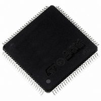
ST10R172LT1 STMicroelectronics, ST10R172LT1 Datasheet - Page 57

ST10R172LT1
Manufacturer Part Number
ST10R172LT1
Description
MCU 16BIT ROMLESS LV 100TQFP
Manufacturer
STMicroelectronics
Series
ST10r
Datasheet
1.ST10R172LT6.pdf
(68 pages)
Specifications of ST10R172LT1
Core Processor
ST10
Core Size
16-Bit
Speed
50MHz
Connectivity
EBI/EMI, SSP, UART/USART
Peripherals
POR, PWM, WDT
Number Of I /o
77
Program Memory Type
ROMless
Ram Size
1K x 8
Voltage - Supply (vcc/vdd)
3 V ~ 3.6 V
Oscillator Type
Internal
Operating Temperature
0°C ~ 70°C
Package / Case
100-TQFP, 100-VQFP
Controller Family/series
ST10
No. Of I/o's
77
Ram Memory Size
1KB
Cpu Speed
50MHz
No. Of Timers
5
Embedded Interface Type
SPI, USART
No. Of Pwm Channels
1
Rohs Compliant
Yes
Processor Series
ST10R1x
Core
ST10
Data Bus Width
16 bit
Data Ram Size
1 KB
Interface Type
SSP, USART
Maximum Clock Frequency
50 MHz
Number Of Programmable I/os
77
Number Of Timers
5
Maximum Operating Temperature
+ 70 C
Mounting Style
SMD/SMT
Minimum Operating Temperature
0 C
On-chip Adc
8 bit
Lead Free Status / RoHS Status
Lead free / RoHS Compliant
Eeprom Size
-
Program Memory Size
-
Data Converters
-
Lead Free Status / Rohs Status
In Transition
Available stocks
Company
Part Number
Manufacturer
Quantity
Price
Company:
Part Number:
ST10R172LT1
Manufacturer:
TI
Quantity:
101
Company:
Part Number:
ST10R172LT1
Manufacturer:
STMicroelectronics
Quantity:
10 000
Company:
Part Number:
ST10R172LT1VJ029CNX
Manufacturer:
ST
Quantity:
50
Company:
Part Number:
ST10R172LT1VJ052JNX
Manufacturer:
ST
Quantity:
34
15.3.5 CLKOUT and READY/READY
V
Parameter
CLKOUT cycle time
CLKOUT high time
CLKOUT low time
CLKOUT rise time
CLKOUT fall time
CLKOUT rising edge to
ALE falling edge
Synchronous READY
setup time to CLKOUT
Synchronous READY
hold time after CLKOUT
Asynchronous READY
low time
Asynchronous READY
setup time
Asynchronous READY
hold time
Async. READY hold time
after RD, WR high (Demulti-
plexed Bus)
DD
1) Measured between 0.3 and 2.7 volts
2) These timings assure recognition at a specific clock edge for test purposes only.
3) Demultiplexed bus is the worst case. For multiplexed bus, 2TCL should be added
= 3.3 V
to the maximum values. This adds even more time for deactivating READY.
2t
2
A
2)
and t
3)2
0.3 V
C
1
1)
refer to the following bus cycle, t
V
SS
Table 16 CLKOUT and READY/READY
Symbol
t
t
t
t
t
t
t
t
t
t
t
t
29
30
31
32
33
34
35
36
37
58
59
60
= 0 V
CC 20
CC 5
CC 5
CC –
CC –
CC -3 +
SR 9
SR 0
SR 27
SR 9
SR 0
SR 0
Max. CPU Clock
= 50 MHz
min.
t
A
ST10R172L - ELECTRICAL CHARACTERISTICS
T
max.
20
–
–
3
3
5 +
–
–
–
–
–
0
+ 2
1
1
A
= -40°C to +85 °C
t
t
A
F
A
+
refers to the current bus cycle.
t
c
+
t
F
3
Variable CPU Clock
1/2TCL = 1 to 50 MHz
min.
2TCL
TCL – 5
TCL – 5
–
–
-3 +
9
0
2TCL + 7
9
0
0
t
A
C
L
= 50 pF
max.
2TCL
–
–
3
3
5 +
–
–
–
–
–
TCL - 10
+ 2
1
1
t
t
A
A
+
t
c
+
t
F
3
ns
ns
ns
ns
ns
ns
ns
ns
ns
ns
ns
ns
57/68
1


