MC908GT16CBE Freescale Semiconductor, MC908GT16CBE Datasheet - Page 113
MC908GT16CBE
Manufacturer Part Number
MC908GT16CBE
Description
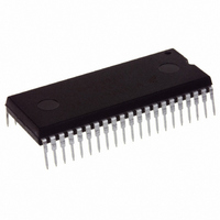
IC MCU 16K FLASH 8MHZ SPI 42SDIP
Manufacturer
Freescale Semiconductor
Series
HC08r
Datasheet
1.MC908GT8CFBE.pdf
(292 pages)
Specifications of MC908GT16CBE
Core Processor
HC08
Core Size
8-Bit
Speed
8MHz
Connectivity
SCI, SPI
Peripherals
LVD, POR, PWM
Number Of I /o
36
Program Memory Size
16KB (16K x 8)
Program Memory Type
FLASH
Ram Size
512 x 8
Voltage - Supply (vcc/vdd)
2.7 V ~ 5.5 V
Data Converters
A/D 8x8b
Oscillator Type
Internal
Operating Temperature
-40°C ~ 85°C
Package / Case
42-DIP (0.600", 15.24mm)
Controller Family/series
HC08
No. Of I/o's
34
Ram Memory Size
512Byte
Cpu Speed
8MHz
No. Of Timers
2
Embedded Interface Type
I2C, SCI, SPI
Rohs Compliant
Yes
Processor Series
HC08GT
Core
HC08
Data Bus Width
8 bit
Data Ram Size
512 B
Interface Type
SCI, SPI
Maximum Clock Frequency
8 MHz
Number Of Programmable I/os
30
Number Of Timers
4
Operating Supply Voltage
0 V to 5 V
Maximum Operating Temperature
+ 85 C
Mounting Style
Through Hole
Development Tools By Supplier
FSICEBASE, DEMO908GZ60E, M68CBL05CE, M68EML08GPGTE
Minimum Operating Temperature
- 40 C
On-chip Adc
8 bit, 8 Channel
Package
42SPDIP
Family Name
HC08
Maximum Speed
8 MHz
Lead Free Status / RoHS Status
Lead free / RoHS Compliant
Eeprom Size
-
Lead Free Status / Rohs Status
Details


Chapter 10
Low-Voltage Inhibit (LVI)
10.1 Introduction
This section describes the low-voltage inhibit (LVI) module, which monitors the voltage on the V
and can force a reset when the V
10.2 Features
Features of the LVI module include:
10.3 Functional Description
Figure 10-1
contains a bandgap reference circuit and comparator. Clearing the LVI power disable bit, LVIPWRD,
enables the LVI to monitor V
module to generate a reset when V
bit, LVISTOP, enables the LVI to operate in stop mode. Setting the LVI 5-V or 3-V trip point bit, LVI5OR3,
enables the trip point voltage, V
enables the trip point voltage, V
in
Freescale Semiconductor
Chapter 20 Electrical
•
•
•
Programmable LVI reset
Selectable LVI trip voltage
Programmable stop mode operation
shows the structure of the LVI module. The LVI is enabled out of reset. The LVI module
After a power-on reset (POR) the LVI’s default mode of operation is 3 V. If
a 5-V system is used, the user must set the LVI5OR3 bit to raise the trip
point to 5-V operation. Note that this must be done after every power-on
reset since the default will revert back to 3-V mode after each power-on
reset. If the V
3-V mode trip voltage when POR is released, the part will operate because
V
taken to ensure that V
released.
If the user requires 5-V mode and sets the LVI5OR3 bit after a power-on
reset while the V
microcontroller unit (MCU) will immediately go into reset. The LVI in this
case will hold the part in reset until either V
point, V
V which will re-trigger the power-on reset and reset the trip point to 3-V
operation.
TRIPF
MC68HC908GT16 • MC68HC908GT8 • MC68HC08GT16 Data Sheet, Rev. 5.0
defaults to 3-V mode after a POR. So, in a 5-V system care must be
TRIPR
Specifications.
, which will release reset or V
DD
DD
TRIPF
supply is below the 5-V mode trip voltage but above the
DD
TRIPF
voltage. Clearing the LVI reset disable bit, LVIRSTD, enables the LVI
DD
supply is not above the V
DD
, to be configured for 3-V operation. The actual trip points are shown
voltage falls below the LVI trip falling voltage, V
, to be configured for 5-V operation. Clearing the LVI5OR3 bit
DD
falls below a voltage, V
is above the 5-V mode trip voltage after POR is
NOTE
DD
DD
decreases to approximately 0
goes above the rising 5-V trip
TRIPR
TRIPF
for 5-V mode, the
. Setting the LVI enable in stop mode
TRIPF
.
DD
pin
113
Related parts for MC908GT16CBE
Image
Part Number
Description
Manufacturer
Datasheet
Request
R

Part Number:
Description:
Manufacturer:
Freescale Semiconductor, Inc
Datasheet:
Part Number:
Description:
Manufacturer:
Freescale Semiconductor, Inc
Datasheet:
Part Number:
Description:
Manufacturer:
Freescale Semiconductor, Inc
Datasheet:
Part Number:
Description:
Manufacturer:
Freescale Semiconductor, Inc
Datasheet:
Part Number:
Description:
Manufacturer:
Freescale Semiconductor, Inc
Datasheet:
Part Number:
Description:
Manufacturer:
Freescale Semiconductor, Inc
Datasheet:
Part Number:
Description:
Manufacturer:
Freescale Semiconductor, Inc
Datasheet:
Part Number:
Description:
Manufacturer:
Freescale Semiconductor, Inc
Datasheet:
Part Number:
Description:
Manufacturer:
Freescale Semiconductor, Inc
Datasheet:
Part Number:
Description:
Manufacturer:
Freescale Semiconductor, Inc
Datasheet:
Part Number:
Description:
Manufacturer:
Freescale Semiconductor, Inc
Datasheet:
Part Number:
Description:
Manufacturer:
Freescale Semiconductor, Inc
Datasheet:
Part Number:
Description:
Manufacturer:
Freescale Semiconductor, Inc
Datasheet:
Part Number:
Description:
Manufacturer:
Freescale Semiconductor, Inc
Datasheet:
Part Number:
Description:
Manufacturer:
Freescale Semiconductor, Inc
Datasheet: