M30281F8HP#D5 Renesas Electronics America, M30281F8HP#D5 Datasheet - Page 181
M30281F8HP#D5
Manufacturer Part Number
M30281F8HP#D5
Description
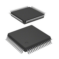
IC M16C MCU FLASH 64K 64-LQFP
Manufacturer
Renesas Electronics America
Series
M16C™ M16C/Tiny/28r
Datasheet
1.M30280F6HPU9.pdf
(425 pages)
Specifications of M30281F8HP#D5
Core Processor
M16C/60
Core Size
16-Bit
Speed
20MHz
Connectivity
I²C, IEBus, SIO, UART/USART
Peripherals
DMA, POR, PWM, Voltage Detect, WDT
Number Of I /o
55
Program Memory Size
64KB (64K x 8)
Program Memory Type
FLASH
Ram Size
4K x 8
Voltage - Supply (vcc/vdd)
2.7 V ~ 5.5 V
Data Converters
A/D 13x10b
Oscillator Type
Internal
Operating Temperature
-20°C ~ 85°C
Package / Case
64-LQFP
For Use With
M30290T2-CPE - EMULATOR COMPACT M16C/26A/28/29M30290T2-CPE-HP - EMULATOR COMPACT FOR M16C/TINY
Lead Free Status / RoHS Status
Contains lead / RoHS non-compliant
Eeprom Size
-
Available stocks
Company
Part Number
Manufacturer
Quantity
Price

Part Number:
M30281F8HP#D5M30281F8HP#U3
Manufacturer:
Renesas Electronics America
Quantity:
10 000


M
R
R
1
e
E
Table 13.9 Phase-delayed Waveform Output Mode Specifications
. v
6
J
Waveform output start condition
Waveform output stop condition
Interrupt request
OUTC1j pin
Selectable function
NOTES:
Output waveform
13.5.2 Phase-Delayed Waveform Output Mode
C
0
2
9
Output signal level of the OUTC1j pin is inversed every time the base timer value matches the G1POj
register value ( j=0 to 7). Table 13.9 lists specifications of phase-delayed waveform mode. Figure 13.23
shows an example of phase-delayed waveform mode operation.
2 /
1. The OUTC1
0 .
B
8
0
0
0
G
4
J
7
a
o r
0 -
. n
u
2
(1)
p
3
Item
0
, 1
0
(
M
2
1
0
0
0
6
to OUTC1
7
C
2 /
page 159
, 8
M
1
7
6
pins.
C
2 /
f o
8
• Free-running operation
• The base timer is cleared to "0000
The IFEj bit in the G1FE register is set to "1" (channel j function enabled)
The IFEj bit is set to "0" (channel j function disabled)
The G1IRj bit in the interrupt request register is set to "1" when the base timer
value matches the G1POj register value. (See Figure 13.23)
Pulse signal output pin
• Default value set function : Set starting waveform output level
• Inverse output function : Waveform output signal is inversed and provided
3
) B
(the RST1, RST2, and RST4 bits of the G1BCR1 and G1BCR0 registers are set
Cycle
8
to "0" (no reset))
"H" and "L" width
following register
(a) G1PO0 register (enabled by setting RST1 bit to "1", and RST4 and RST2 bits to "0"), or
(b) G1BTRR register (enabled by setting RST4 bit to "1", and RST2 and RST1 bits to "0")
Cycle
"H" and "L" width
from the OUTC1j pin
5
n : setting value of either G1PO0 register or G1BTRR register
:
:
:
:
65536 x 2
65536
2(n+2)
f
f
n+2
f
BT1
BT1
BT1
f
BT1
Specification
16
" by matching the base timer with either
13. Timer S
Related parts for M30281F8HP#D5
Image
Part Number
Description
Manufacturer
Datasheet
Request
R

Part Number:
Description:
KIT STARTER FOR M16C/29
Manufacturer:
Renesas Electronics America
Datasheet:

Part Number:
Description:
KIT STARTER FOR R8C/2D
Manufacturer:
Renesas Electronics America
Datasheet:

Part Number:
Description:
R0K33062P STARTER KIT
Manufacturer:
Renesas Electronics America
Datasheet:

Part Number:
Description:
KIT STARTER FOR R8C/23 E8A
Manufacturer:
Renesas Electronics America
Datasheet:

Part Number:
Description:
KIT STARTER FOR R8C/25
Manufacturer:
Renesas Electronics America
Datasheet:

Part Number:
Description:
KIT STARTER H8S2456 SHARPE DSPLY
Manufacturer:
Renesas Electronics America
Datasheet:

Part Number:
Description:
KIT STARTER FOR R8C38C
Manufacturer:
Renesas Electronics America
Datasheet:

Part Number:
Description:
KIT STARTER FOR R8C35C
Manufacturer:
Renesas Electronics America
Datasheet:

Part Number:
Description:
KIT STARTER FOR R8CL3AC+LCD APPS
Manufacturer:
Renesas Electronics America
Datasheet:
Part Number:
Description:
KIT STARTER FOR RX610
Manufacturer:
Renesas Electronics America
Datasheet:

Part Number:
Description:
KIT STARTER FOR R32C/118
Manufacturer:
Renesas Electronics America
Datasheet:

Part Number:
Description:
KIT DEV RSK-R8C/26-29
Manufacturer:
Renesas Electronics America
Datasheet:

Part Number:
Description:
KIT STARTER FOR SH7124
Manufacturer:
Renesas Electronics America
Datasheet:

Part Number:
Description:
KIT STARTER FOR H8SX/1622
Manufacturer:
Renesas Electronics America
Datasheet:

Part Number:
Description:
KIT DEV FOR SH7203
Manufacturer:
Renesas Electronics America
Datasheet: