M30281F8HP#D5 Renesas Electronics America, M30281F8HP#D5 Datasheet - Page 286
M30281F8HP#D5
Manufacturer Part Number
M30281F8HP#D5
Description
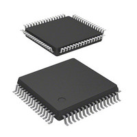
IC M16C MCU FLASH 64K 64-LQFP
Manufacturer
Renesas Electronics America
Series
M16C™ M16C/Tiny/28r
Datasheet
1.M30280F6HPU9.pdf
(425 pages)
Specifications of M30281F8HP#D5
Core Processor
M16C/60
Core Size
16-Bit
Speed
20MHz
Connectivity
I²C, IEBus, SIO, UART/USART
Peripherals
DMA, POR, PWM, Voltage Detect, WDT
Number Of I /o
55
Program Memory Size
64KB (64K x 8)
Program Memory Type
FLASH
Ram Size
4K x 8
Voltage - Supply (vcc/vdd)
2.7 V ~ 5.5 V
Data Converters
A/D 13x10b
Oscillator Type
Internal
Operating Temperature
-20°C ~ 85°C
Package / Case
64-LQFP
For Use With
M30290T2-CPE - EMULATOR COMPACT M16C/26A/28/29M30290T2-CPE-HP - EMULATOR COMPACT FOR M16C/TINY
Lead Free Status / RoHS Status
Contains lead / RoHS non-compliant
Eeprom Size
-
Available stocks
Company
Part Number
Manufacturer
Quantity
Price

Part Number:
M30281F8HP#D5M30281F8HP#U3
Manufacturer:
Renesas Electronics America
Quantity:
10 000


R
R
M
16.5 I
e
E
1
. v
J
6
The S10 register monitors the I
use the 6 low-order bits for read only.
16.5.1 Bit 0: Last Receive Bit (LRB)
16.5.2 Bit 1: General Call Detection Flag (ADR0)
16.5.3 Bit 2: Slave Address Comparison Flag (AAS)
16.5.4 Bit 3: Arbitration Lost Detection Flag (AL)
0
C
2
9
The LRB bit stores the last bit value of received data. It can also be used to confirm whether ACK is
received. If the ACK-CLK bit in the S20 register is set to "1" (with ACK clock) and ACK is returned when
the ACK clock is generated, the LRB bit is set to “0”. If ACK is not returned, the LRB bit is set to “1”. When
the ACK-CLK bit is set to "0" (no ACK clock), the last bit value of received data is input. When writing data
to the S00 register, the LRB bit is set to "0".
When the ALS bit in the S1D0 register is set to “0” (addressing format), this ADR0 flag is set to “1” by
receiving the general calls
The ADR0 flag is set to “0” when STOP or START conditions is detected or when the IHR bit in the S1D0
register is set to "1" (reset).
NOTES:
The AAS flag indicates a comparison result of the slave address data after enabled by setting the ALS bit
in the S1D0 register to “0” (addressing format).
The AAS flag is set to "1" when the 7 bits of the address data are matched with the slave address stored
into the S0D0 register, or when a general call is received, in slave receive mode. The AAS flag is set to 0"
by writing data to the S00 register. When the ES0 bit in the S1D0 register is set to "0" (I
disabled) or when the IHR bit in the S1D0 register is set to "1" (reset), the AAS flag is also set to "0".
In master transmit mode, if an "L" signal is applied to the SDA pin by other than a microcomputer, the AL
flag is set to "1" by determining that the arbitration is los and the TRX bit in the S10 register is set to "0"
(receive mode) at the same time. The MST bit in the S10 register is set to "0" (slave mode) after transfer-
ring the bytes which lost the arbitration.
The arbitration lost can be detected only in master transmit mode. When writing data to the S00 register,
the AL flag is set to "0". When the ES0 bit in the S1D0 register is set to "0" (I
when the IHR bit in the S1D0 register is set to "1" (reset), the AL flag is set to "0".
NOTES:
0 .
B
2 /
0
0
8
0
1. Arbitration lost: communication disabled as a master
2
1. General call: A master device transmits the general call address “00
4
J
G
C0 Status Register (S10 register)
7
a
o r
0 -
master device transmits the general call, all slave devices receive the controlled data after general
call.
. n
u
2
3
0
p
, 1
0
(
M
2
0
1
0
6
7
C
2 /
page 264
, 8
M
1
6
(1)
C
,whose address data are all “0”, in slave mode.
f o
2 /
2
8
C bus interface status. When using the S10 register to check the status,
3
) B
8
5
(1)
16. MULTI-MASTER I
2
C bus interface disabled) or
16
” to all slaves. When the
2
2
C bus INTERFACE
C bus interface
Related parts for M30281F8HP#D5
Image
Part Number
Description
Manufacturer
Datasheet
Request
R

Part Number:
Description:
KIT STARTER FOR M16C/29
Manufacturer:
Renesas Electronics America
Datasheet:

Part Number:
Description:
KIT STARTER FOR R8C/2D
Manufacturer:
Renesas Electronics America
Datasheet:

Part Number:
Description:
R0K33062P STARTER KIT
Manufacturer:
Renesas Electronics America
Datasheet:

Part Number:
Description:
KIT STARTER FOR R8C/23 E8A
Manufacturer:
Renesas Electronics America
Datasheet:

Part Number:
Description:
KIT STARTER FOR R8C/25
Manufacturer:
Renesas Electronics America
Datasheet:

Part Number:
Description:
KIT STARTER H8S2456 SHARPE DSPLY
Manufacturer:
Renesas Electronics America
Datasheet:

Part Number:
Description:
KIT STARTER FOR R8C38C
Manufacturer:
Renesas Electronics America
Datasheet:

Part Number:
Description:
KIT STARTER FOR R8C35C
Manufacturer:
Renesas Electronics America
Datasheet:

Part Number:
Description:
KIT STARTER FOR R8CL3AC+LCD APPS
Manufacturer:
Renesas Electronics America
Datasheet:
Part Number:
Description:
KIT STARTER FOR RX610
Manufacturer:
Renesas Electronics America
Datasheet:

Part Number:
Description:
KIT STARTER FOR R32C/118
Manufacturer:
Renesas Electronics America
Datasheet:

Part Number:
Description:
KIT DEV RSK-R8C/26-29
Manufacturer:
Renesas Electronics America
Datasheet:

Part Number:
Description:
KIT STARTER FOR SH7124
Manufacturer:
Renesas Electronics America
Datasheet:

Part Number:
Description:
KIT STARTER FOR H8SX/1622
Manufacturer:
Renesas Electronics America
Datasheet:

Part Number:
Description:
KIT DEV FOR SH7203
Manufacturer:
Renesas Electronics America
Datasheet: