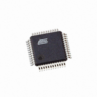
AT91SAM7S32-AU-001 Atmel, AT91SAM7S32-AU-001 Datasheet - Page 760

AT91SAM7S32-AU-001
Manufacturer Part Number
AT91SAM7S32-AU-001
Description
IC ARM7 MCU 32BIT 32K 48LQFP
Manufacturer
Atmel
Series
AT91SAMr
Specifications of AT91SAM7S32-AU-001
Core Processor
ARM7
Core Size
16/32-Bit
Speed
55MHz
Connectivity
I²C, SPI, SSC, UART/USART
Peripherals
Brown-out Detect/Reset, POR, PWM, WDT
Number Of I /o
21
Program Memory Size
32KB (32K x 8)
Program Memory Type
FLASH
Ram Size
8K x 8
Voltage - Supply (vcc/vdd)
1.65 V ~ 1.95 V
Data Converters
A/D 8x10b
Oscillator Type
Internal
Operating Temperature
-40°C ~ 85°C
Package / Case
48-LQFP
For Use With
AT91SAM7S-EK - KIT EVAL FOR ARM AT91SAM7S
Lead Free Status / RoHS Status
Lead free / RoHS Compliant
Eeprom Size
-
Other names
AT91SAM7S32-AU001
Available stocks
Company
Part Number
Manufacturer
Quantity
Price
- Current page: 760 of 779
- Download datasheet (11Mb)
750
Version
6175H
AT91SAM7S Series Preliminary
Comments
Overview:
“Features” on page 1
See:
Section 8.6 “AT91SAM7S161/16” on page
Section 9.5 ”Debug Unit”
Section 6. ”I/O Lines
ADC:
AIC:
Debug and Test:
Table 12-2, “AT91SAM7S Series Debug Unit Chip ID,” on page
Table 12.5.5, “ID Code Register,” on page
EFC:
FFPI:
Table
Global update to terms listed below: ≥
Fuse → GPNVM
SFB → SGPB
CFB → CGPB
GFB → GGPB
Section 20.2.5.6 on page 133 &Section 20.3.4.6 on page
PIO:
Section 27.4.5 ”Synchronous Data
PIO User Interface,
PMC:
SPI:
SSC:
TC:
459
updated with indexed offset.
Section 33.6.4 ”TC Channel Mode Register: Capture
TWI:
Section 29. ”Two-wire Interface (TWI)
Important changes to this datasheet include a clarification of Atmel TWI compatibility with I2C Standard.
Section 30. ”Two Wire Interface (TWI)
on the AT91SAM7S16/161 devices.
PWM:
Section 34.6 ”Pulse Width Modulation Controller (PWM) User
“Register
from:
Section 33.6 ”Timer Counter (TC) User
and register offsets indexed.
Section 28.6.4 ”SPI Slave
Table 1-1, “Configuration Summary,” on page 3
Section 23.8.15 ”AIC Spurious Interrupt Vector
Section 34.6.10 on page 494
Section 19.3.3 ”MC Flash Status Register”
“SSC Receive Clock Mode Register” on page
Section 36.6.2 ”ADC Mode
20-6,
Figure 24-2 ”Typical Crystal Connection”
Mapping”, the PWM channel-dependent registers are indexed. See alos, PWM Channel registers
Table 20-7
Table 27-2, “Register Mapping”
Considerations”, JTAG Port Pin, Test Pin, Erase Pin, updated.
(and all of datasheet) Added AT91SAM7S16/161 to product family.
plus
Chip ID updated.
Table
Mode”, Corrected information on OVRES (SPI_SR) and data read in SPI_RDR. 3943
Section 33.6.3 on page 462
Register”, STARTUP and PRESCAL bitfields updated (width expanded).
20-8,
Output”, typo fixed on PIO_OWSR
to
Section 34.6.13 on page
AT91SAM7S512/256/128/64/321/32”, section has been updated.
AT91SAM7S161/16”, section added specific to the TWI implementation
Table
56, updated.
19.
Interface”, register mapping consolidated in
plus
updated
GPNVM2 removed from bit field 10.
updates to footnotes, PIO_PSR, PIO_ODSR, PIO_PDSR
Table
424, typo corrected in STTDLY bit field.
Register”, bitfield typo corrected
Mode”, bit field 15 and WAVE bit field description updated.
141, security bit restraint on access to FFPI explained
20-17,
to
Interface”, in the Offset column in
496.
51, updated.
Section 33.6.13 on page
Table 20-18
and
Table 20-20
Table 33-4 on page
476, register names
updated
Table 34-2,
6175K–ATARM–30-Aug-10
Change
Request
Ref.
rfo
4325
5063
4749
4325/rfo
4464
4410
3933
4744
3289
3974
3861
4478
4583
4247
rfo
4486
Related parts for AT91SAM7S32-AU-001
Image
Part Number
Description
Manufacturer
Datasheet
Request
R

Part Number:
Description:
Manufacturer:
ATMEL Corporation
Datasheet:

Part Number:
Description:
AT91 ARM Thumb-based Microcontrollers
Manufacturer:
ATMEL [ATMEL Corporation]
Datasheet:

Part Number:
Description:
IC ARM7 MCU FLASH 32K 48QFN
Manufacturer:
Atmel
Datasheet:

Part Number:
Description:
IC MCU ARM7 32KB FLASH 48LQFP
Manufacturer:
Atmel
Datasheet:

Part Number:
Description:
IC MCU ARM7 32KB FLASH 48-VQFN
Manufacturer:
Atmel
Datasheet:

Part Number:
Description:
DEV KIT FOR AVR/AVR32
Manufacturer:
Atmel
Datasheet:

Part Number:
Description:
INTERVAL AND WIPE/WASH WIPER CONTROL IC WITH DELAY
Manufacturer:
ATMEL Corporation
Datasheet:

Part Number:
Description:
Low-Voltage Voice-Switched IC for Hands-Free Operation
Manufacturer:
ATMEL Corporation
Datasheet:

Part Number:
Description:
MONOLITHIC INTEGRATED FEATUREPHONE CIRCUIT
Manufacturer:
ATMEL Corporation
Datasheet:

Part Number:
Description:
AM-FM Receiver IC U4255BM-M
Manufacturer:
ATMEL Corporation
Datasheet:

Part Number:
Description:
Monolithic Integrated Feature Phone Circuit
Manufacturer:
ATMEL Corporation
Datasheet:

Part Number:
Description:
Multistandard Video-IF and Quasi Parallel Sound Processing
Manufacturer:
ATMEL Corporation
Datasheet:


