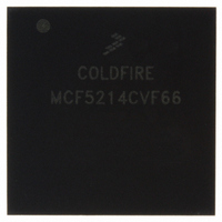
MCF5214CVF66 Freescale Semiconductor, MCF5214CVF66 Datasheet - Page 533

MCF5214CVF66
Manufacturer Part Number
MCF5214CVF66
Description
IC MPU 32BIT COLDF 256-MAPBGA
Manufacturer
Freescale Semiconductor
Series
MCF521xr
Datasheet
1.MCF5216CVM66J.pdf
(766 pages)
Specifications of MCF5214CVF66
Core Processor
Coldfire V2
Core Size
32-Bit
Speed
66MHz
Connectivity
CAN, EBI/EMI, I²C, SPI, UART/USART
Peripherals
DMA, LVD, POR, PWM, WDT
Number Of I /o
142
Program Memory Size
256KB (256K x 8)
Program Memory Type
FLASH
Ram Size
64K x 8
Voltage - Supply (vcc/vdd)
2.7 V ~ 3.6 V
Data Converters
A/D 8x12b
Oscillator Type
Internal
Operating Temperature
-40°C ~ 85°C
Package / Case
256-MAPBGA
Package
256MA-BGA
Device Core
ColdFire
Family Name
MCF521x
Maximum Speed
66 MHz
Operating Supply Voltage
3.3 V
Data Bus Width
32 Bit
Number Of Programmable I/os
142
Interface Type
QSPI/UART/I2C/CAN
On-chip Adc
8-chx10-bit
Number Of Timers
8
Lead Free Status / RoHS Status
Contains lead / RoHS non-compliant
Eeprom Size
-
Available stocks
Company
Part Number
Manufacturer
Quantity
Price
Company:
Part Number:
MCF5214CVF66
Manufacturer:
Freescale Semiconductor
Quantity:
10 000
Company:
Part Number:
MCF5214CVF66J
Manufacturer:
Freescale Semiconductor
Quantity:
10 000
- Current page: 533 of 766
- Download datasheet (9Mb)
27.5.3.2 Reset Configuration Register (RCON)
At reset, RCON determines the default operation of certain chip functions. All default functions defined
by the RCON values can only be overridden during reset configuration (see
Configuration”) if the external RCON pin is asserted. RCON is a read-only register.
Freescale Semiconductor
Bits
2–0
15–10
4
3
Bits
9–8
7–6
5
Address
Reset
Field
R/W
Name
BME
BMT
—
RLOAD
Name
RCSC
15
—
—
Reserved, should be cleared.
Bus monitor enable. This read/write bit enables the bus monitor to operate during external bus
cycles.
0 Bus monitor disabled for external bus cycles.
1 Bus monitor enabled for external bus cycles.
Table 27-2
Bus monitor timing. This field selects the timeout period (in system clocks) for the bus monitor.
000 65536
001 32768
010 16384
011 8192
100 4096
101 2048
110 1024
111 512
Table 27-2
MCF5282 and MCF5216 ColdFire Microcontroller User’s Manual, Rev. 3
Reserved, should be cleared.
Chip select configuration. Reflects the default chip select configuration. The default function
of the chip select configuration can be overridden during reset configuration.
00 PF[7:5] = A[23:21] (This is the value used for this device.)
01 PF[7] = CS6 / PF[6:5] = A[22:21]
10 PF[7:6] = CS6, CS5 / PF[5] = A[21]
11 PF[7:5] = CS6, CS5, CS4
Reserved, should be cleared.
Pad driver load. Reflects the default pad driver strength configuration.
0 Partial drive strength
1 Full drive strength (This is the value used for this device.)
—
Figure 27-3. Reset Configuration Register (RCON)
Table 27-4. CCR Field Descriptions (continued)
shows the read/write accessibility of this write-once bit.
shows the read/write accessibility of this write-once bit.
Table 27-5. RCON Field Descriptions
10
9
RCSC
0000_0000_1110_0000
IPSBAR + 0x11_0008
8
7
—
R
Description
Description
6
RLOAD BOOTPS BOOTSEL
5
4
3
Chip Configuration Module (CCM)
2
Section 27.6.1, “Reset
— MODE
1
0
27-5
Related parts for MCF5214CVF66
Image
Part Number
Description
Manufacturer
Datasheet
Request
R
Part Number:
Description:
Manufacturer:
Freescale Semiconductor, Inc
Datasheet:
Part Number:
Description:
Manufacturer:
Freescale Semiconductor, Inc
Datasheet:
Part Number:
Description:
Manufacturer:
Freescale Semiconductor, Inc
Datasheet:
Part Number:
Description:
Manufacturer:
Freescale Semiconductor, Inc
Datasheet:
Part Number:
Description:
Manufacturer:
Freescale Semiconductor, Inc
Datasheet:
Part Number:
Description:
Manufacturer:
Freescale Semiconductor, Inc
Datasheet:
Part Number:
Description:
Manufacturer:
Freescale Semiconductor, Inc
Datasheet:
Part Number:
Description:
Manufacturer:
Freescale Semiconductor, Inc
Datasheet:
Part Number:
Description:
Manufacturer:
Freescale Semiconductor, Inc
Datasheet:
Part Number:
Description:
Manufacturer:
Freescale Semiconductor, Inc
Datasheet:
Part Number:
Description:
Manufacturer:
Freescale Semiconductor, Inc
Datasheet:
Part Number:
Description:
Manufacturer:
Freescale Semiconductor, Inc
Datasheet:
Part Number:
Description:
Manufacturer:
Freescale Semiconductor, Inc
Datasheet:
Part Number:
Description:
Manufacturer:
Freescale Semiconductor, Inc
Datasheet:
Part Number:
Description:
Manufacturer:
Freescale Semiconductor, Inc
Datasheet:


