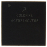
MCF5214CVF66 Freescale Semiconductor, MCF5214CVF66 Datasheet - Page 559

MCF5214CVF66
Manufacturer Part Number
MCF5214CVF66
Description
IC MPU 32BIT COLDF 256-MAPBGA
Manufacturer
Freescale Semiconductor
Series
MCF521xr
Datasheet
1.MCF5216CVM66J.pdf
(766 pages)
Specifications of MCF5214CVF66
Core Processor
Coldfire V2
Core Size
32-Bit
Speed
66MHz
Connectivity
CAN, EBI/EMI, I²C, SPI, UART/USART
Peripherals
DMA, LVD, POR, PWM, WDT
Number Of I /o
142
Program Memory Size
256KB (256K x 8)
Program Memory Type
FLASH
Ram Size
64K x 8
Voltage - Supply (vcc/vdd)
2.7 V ~ 3.6 V
Data Converters
A/D 8x12b
Oscillator Type
Internal
Operating Temperature
-40°C ~ 85°C
Package / Case
256-MAPBGA
Package
256MA-BGA
Device Core
ColdFire
Family Name
MCF521x
Maximum Speed
66 MHz
Operating Supply Voltage
3.3 V
Data Bus Width
32 Bit
Number Of Programmable I/os
142
Interface Type
QSPI/UART/I2C/CAN
On-chip Adc
8-chx10-bit
Number Of Timers
8
Lead Free Status / RoHS Status
Contains lead / RoHS non-compliant
Eeprom Size
-
Available stocks
Company
Part Number
Manufacturer
Quantity
Price
Company:
Part Number:
MCF5214CVF66
Manufacturer:
Freescale Semiconductor
Quantity:
10 000
Company:
Part Number:
MCF5214CVF66J
Manufacturer:
Freescale Semiconductor
Quantity:
10 000
- Current page: 559 of 766
- Download datasheet (9Mb)
Freescale Semiconductor
Bit(s)
9–6
5–0
Externally triggered single-scan
Externally triggered continuous-scan
Interval timer trigger single-scan
Interval timer continuous-scan
Software-initiated single-scan
Software-initiated continuous-scan
Externally gated single-scan
Externally gated continuous-scan
Name
CWP
QS
MCF5282 and MCF5216 ColdFire Microcontroller User’s Manual, Rev. 3
Table 28-10. QASR0 Field Descriptions (continued)
QS[9:6]
0000
0001
0010
0011
0100
0101
0110
Queue status. Indicates the current condition of queue 1 and queue 2. The two most
significant bits are associated primarily with queue 1, and the remaining two bits are
associated with queue 2. Because the priority scheme between the two queues
causes the status to be interlinked, the status bits must be considered as one 4-bit
field.
queue 1 and queue 2.
The queue status field is affected by QADC stop mode. Because all of the analog logic
and control registers are reset, the queue status field is reset to queue 1 idle, queue
2 idle.
During debug mode, the queue status field is not modified. The queue status field
retains the status it held prior to freezing. As a result, the queue status can show
queue 1 active, queue 2 idle, even though neither queue is being executed during
freeze.
Command word pointer. Denotes which CCW is executing at present or was last
completed. CWP is a read-only field with a valid range of 0 to 63; write operations have
no effect.
During stop mode, CWP is reset to 0 because the control registers and the analog
logic are reset. When debug mode is entered, CWP is not changed; it points to the last
executed CCW.
Scan Mode
Table 28-11. CCW Pause Bit Response
Table 28-12
Table 28-12. Queue Status
Queue 1 idle, queue 2 idle
Queue 1 idle, queue 2 paused
Queue 1 idle, queue 2 active
Queue 1 idle, queue 2 trigger pending
Queue 1 paused, queue 2 idle
Queue 1 paused, queue 2 paused
Queue 1 paused, queue 2 active
shows the bits in the QS field and how they denote the status of
Queue 1/Queue 2 States
Queue Operation
Continues
Continues
Continues
Continues
Description
Pauses
Pauses
Pauses
Pauses
Queued Analog-to-Digital Converter (QADC)
PF Asserts?
Yes
Yes
Yes
Yes
Yes
Yes
No
No
28-21
Related parts for MCF5214CVF66
Image
Part Number
Description
Manufacturer
Datasheet
Request
R
Part Number:
Description:
Manufacturer:
Freescale Semiconductor, Inc
Datasheet:
Part Number:
Description:
Manufacturer:
Freescale Semiconductor, Inc
Datasheet:
Part Number:
Description:
Manufacturer:
Freescale Semiconductor, Inc
Datasheet:
Part Number:
Description:
Manufacturer:
Freescale Semiconductor, Inc
Datasheet:
Part Number:
Description:
Manufacturer:
Freescale Semiconductor, Inc
Datasheet:
Part Number:
Description:
Manufacturer:
Freescale Semiconductor, Inc
Datasheet:
Part Number:
Description:
Manufacturer:
Freescale Semiconductor, Inc
Datasheet:
Part Number:
Description:
Manufacturer:
Freescale Semiconductor, Inc
Datasheet:
Part Number:
Description:
Manufacturer:
Freescale Semiconductor, Inc
Datasheet:
Part Number:
Description:
Manufacturer:
Freescale Semiconductor, Inc
Datasheet:
Part Number:
Description:
Manufacturer:
Freescale Semiconductor, Inc
Datasheet:
Part Number:
Description:
Manufacturer:
Freescale Semiconductor, Inc
Datasheet:
Part Number:
Description:
Manufacturer:
Freescale Semiconductor, Inc
Datasheet:
Part Number:
Description:
Manufacturer:
Freescale Semiconductor, Inc
Datasheet:
Part Number:
Description:
Manufacturer:
Freescale Semiconductor, Inc
Datasheet:


