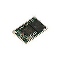
DVK-BTM411 Laird Technologies, DVK-BTM411 Datasheet - Page 33

DVK-BTM411
Manufacturer Part Number
DVK-BTM411
Description
BLUETOOTH EVAL BOARD BTM411
Manufacturer
Laird Technologies
Type
Transceiverr
Specifications of DVK-BTM411
Frequency
2.4GHz
Wireless Frequency
2.402 GHz to 2.48 GHz
Interface Type
UART
Data Rate
2.1 Mbps
Operating Voltage
3 V to 3.3 V
Antenna
Multilayer Ceramic Integrated
Operating Temperature Range
- 30 C to + 70 C
Output Power
4 dBm
Technology/ Type
Development Kit
For Use With/related Products
BTM411
Lead Free Status / RoHS Status
Lead free / RoHS Compliant
Lead Free Status / RoHS Status
Lead free / RoHS Compliant, Lead free / RoHS Compliant
Other names
DVK-BTM411
Available stocks
Company
Part Number
Manufacturer
Quantity
Price
Company:
Part Number:
DVK-BTM411-02
Manufacturer:
LAIRD
Quantity:
2
BTM410/411
Bluetooth
AT COMMAND SET
REFERENCE
33 www.lairdtech.com
®
AT Data Module
Hardware Units (BTM410 / 411)
This section covers S-Registers and AT-Commands that are related to hardware units of a BTM410 or
BTM411 device. For this section, please also refer to the bluecore data sheet [5] for further information.
1. Codec Gain
2. Hardware Units - S Registers
2.9
The BTM410/411 can operate with an external PCM codec. Laird provides a number of different codec
evaluation boards designed for use with the BTM410/411 development kit. For example the ACC-05
is a codec evaluation board based around the Winbond W681360 codec [6]. The platform provides
flexible support for different codec formats (μ-law, A-law and 13 bit linear). If 13 bit linear format is
chosen, then the 13 bit sample will be transmitted over the PCM interface as the MS 13 bits of a 16
bit word. The LS 3 bits may be used to control the output gain of the codec (for example on the
Winbond W681360) and the AT software allows this output gain setting to be controlled using
s-register 589 as described in Table 3.11.
Table 3.11 below gives an overview on S Registers for hardware units except GPIO. For GPIO Registers
please refer to Table 3.13: GPIO S Registers
SPP – S Registers
S Registers for SPP are summarized in Table 3.10.
Register
S0
S100
Register
S589
Default Range
0
15
Default Range
8
-1..15
0..15
0..8
Table 3.11: S Registers for Hardware Units
Table 3.10: S Registers for SPP
Description
Number of RING indication before automatically
answering an incoming connection. A value of 0
disables autoanswer. If -1, then autoanswer on one
RING and do NOT send RING/CONNECT response
to the host. This emulates a serial cable replacement
situation Setting values >= 0, resets S Register 504 to
0 and <0 forces 504 to 1.
If S0 <> 0 and S100 <> 0 then S0 must be < S100. If
a value is entered which violates this rule, then ERROR
29 is sent in response.
If S504 =1 then this register will return -1, regardless
of the actual value stored in non-volatile memory.
Number of RING indications before an auto
disconnection is initiated. A value of 0 disables
this feature. If S0 <> 0 and S100 <> 0 then S0
must be < S100. If a value is entered which violates
this rule, then ERROR 29 is sent in response.
Description
External codec output gain
Laird Technologies


