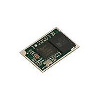
DVK-BTM411 Laird Technologies, DVK-BTM411 Datasheet - Page 47

DVK-BTM411
Manufacturer Part Number
DVK-BTM411
Description
BLUETOOTH EVAL BOARD BTM411
Manufacturer
Laird Technologies
Type
Transceiverr
Specifications of DVK-BTM411
Frequency
2.4GHz
Wireless Frequency
2.402 GHz to 2.48 GHz
Interface Type
UART
Data Rate
2.1 Mbps
Operating Voltage
3 V to 3.3 V
Antenna
Multilayer Ceramic Integrated
Operating Temperature Range
- 30 C to + 70 C
Output Power
4 dBm
Technology/ Type
Development Kit
For Use With/related Products
BTM411
Lead Free Status / RoHS Status
Lead free / RoHS Compliant
Lead Free Status / RoHS Status
Lead free / RoHS Compliant, Lead free / RoHS Compliant
Other names
DVK-BTM411
Available stocks
Company
Part Number
Manufacturer
Quantity
Price
Company:
Part Number:
DVK-BTM411-02
Manufacturer:
LAIRD
Quantity:
2
BTM410/411
Bluetooth
AT COMMAND SET
REFERENCE
47 www.lairdtech.com
®
AT Data Module
Register
S531
S532
S535
S536
S539
S541
S542
S551
Deflt.
0
0
20
0
0
20
4
$3211
Range
0..4
0..7
0..41
0..1
0..1
-43..20
-43..20
$0..$ffff
Description
Specifies the mode on connection establishment.
0 = Normal, that data is exchanged between UART and RF
1 = LOCAL_COMMAND. UART input is parsed by the AT inter-
preter and RF data is discarded
2 = REMOTE_COMMAND. RF input is parsed by the AT interpreter
and UART data is discarded. If S Register 536 is not 1 then this
register cannot be set to 2 and an ERROR will be returned
3 = LOCAL_COMMAND. UART input is parsed by the AT interpret-
er and incoming RF data is sent to the host using the RX<string>
asynchronous response.
4 = LOCAL_COMMAND and on the rf side, the GPIO is auto-
matically sent when there is a change in input. (digital I/O cable
replacement mode)
If non zero then on every connection, a SCO channel (audio) will
be initiated. Bit 0 for HV1, Bit1 for HV2 and Bit2 for HV3. When
the connection is lost, the SCO channel disappears along with it.
Link Supervision Timeout. If units go out of range, then a NO CAR-
RIER message will be sent to the host after the time specified here
When set to 1, a remote device can ‘capture’ the AT parser of this
unit by it sending this module an escape “!!!” sequence. The inter
character timing is set via S Register 12.
If S Register 507 is >= 2, then reading this register will always
return 0 and writing 1 will result in ERROR 33.
When set to 1, in idle mode (S512=1), UART Rx characters are
discarded if DSR is de-asserted.
This sets the power level in dBm when inquiring or paging. Read-
ing this register returns the value stored in non-volatile memory.
As per S541, however reading this register returns the current
power level as set in the base band. The read can be different from
S541because the actual power is set using a lookup table and the
base band rounds down to the nearest value in the table.
This register specifies in each 4 bit nibble, how the outgoing
modem status bits to the remote peer gets its value. Bluetooth®
allows for RTR, RTC, DV and IC bits to be exchanged over an
RFCOMM connection.
Nibble 0..3 specifies the source for RTC
4..7 specifies the source for RTR
8..11 specifies the source for DV (i.e. DCD)
12..15 specifies the source for IC (i.e. RI)
Each nibble can take the following value:-
0 Always set to 0
1 Always set to 1
2 If DCD (pin 8 on module connector) is output then always 1
If DCD is input then 1 if DCD is asserted otherwise 0
3 If RI (pin 6) is output then always 0
If RI is input then 1 if RI is asserted otherwise 0
4 If DSR (pin 10) is asserted then 1 otherwise 0
In the event that a nibble specifies DSR as the source of its state,
be aware that if, S Register 507 is anything other than 0, a de-as-
sertion of DSR will cause the Bluetooth connection to be dropped.
If bits 0..3 and 4..7 are set to 0, then some Bluetooth devices will
use that as a signal to stop sending any data back.
Laird Technologies


