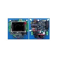
STEVAL-IHP001V3 STMicroelectronics, STEVAL-IHP001V3 Datasheet - Page 40

STEVAL-IHP001V3
Manufacturer Part Number
STEVAL-IHP001V3
Description
BOARD SMART PLUG STM32 SPZB260PR
Manufacturer
STMicroelectronics
Series
Zigbee™ SmartPlugr
Type
Microcontroller, Energy Meteringr
Specifications of STEVAL-IHP001V3
Frequency
2.4GHz
For Use With/related Products
STM32F10x, SPZB260-PRO, STPM01
Lead Free Status / RoHS Status
Lead free / RoHS Compliant
Other names
497-10677
Theory of operation
8.21.1
Figure 24. Timing for providing remote reset request
1. All the time intervals must be longer than 30 ns. t
8.22
40/60
Remote reset
The timing diagram of the operation is shown on the
short as 30 ns.
The internal reset signal is named RRR. Unlike the POR, the RRR signal does not cause
the 30 ms retard restart of analog module and the 120 ms retard restart of digital module.
This signal doesn’t clear the mode signals.
Reading data records
Data records reading will take place most often when there will be an on-board
microcontroller in an application. Such microcontroller will be able to read all measurement
results and all system signals (configuration, calibration, status, mode). Again, the time step
can be as short as 30 ns. There are two phases of reading, called latching and shifting.
Latching is used to sample results into transmission latches. The transmission latches are
the flip-flops that hold the data in the SPI interface. This is done with the active pulse on
SYN when SCS is idle. The length of pulse on SYN must be longer than 2 periods of
measurement clock, i.e. more than 500 ns at 4 MHz.
The shifting starts when SCS become active. In the beginning of this phase another, but
much shorter pulse (30 ns) on SYN should be applied in order to ensure that an internal
transmission serial clock counter is reset to zero. An alternative way is to extend the pulse
on SYN into the second phase of reading. After that reset is done, a 32 serial clocks per
data record should be applied. Up to 8 data records can be read this way. This procedure
can be aborted at any time by deactivation of SCS (see
The first read out byte of data record is least significant byte (LSB) of data value and of
course, the fourth byte is most significant byte (MSB) of data value. Each byte can be further
divided into a pair of 4-bit nibbles, most and least significant nibble (MSN, LSN). This
SYN
SYN
SCLNLC
SCLNLC
SDATD
SDATD
SCS
SCS
t
1
7
Doc ID 10853 Rev 7
→ t
t
2
8
is the reset time, this interval must be longer than 30 ns as well.
t
3
t
4
t
5
t
(1)
6
t
7
Figure
Figure
t
8
24. The time step can be as
t
9
24).
t
10
STPM01


