STEVAL-IHP001V3 STMicroelectronics, STEVAL-IHP001V3 Datasheet - Page 44
STEVAL-IHP001V3
Manufacturer Part Number
STEVAL-IHP001V3
Description
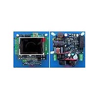
BOARD SMART PLUG STM32 SPZB260PR
Manufacturer
STMicroelectronics
Series
Zigbee™ SmartPlugr
Type
Microcontroller, Energy Meteringr
Specifications of STEVAL-IHP001V3
Frequency
2.4GHz
For Use With/related Products
STM32F10x, SPZB260-PRO, STPM01
Lead Free Status / RoHS Status
Lead free / RoHS Compliant
Other names
497-10677


Theory of operation
8.24
44/60
1.
2.
3.
4.
5.
6.
Permanent writing of the CFG bits
In order to make a permanent set of some CFG bits, the following procedure should be
conducted:
1.
2.
3.
4.
5.
6.
7.
8.
9.
10. clear the OTP shadow latch which was set in step 6;
11. until all wanted CFG bits are permanently set, repeat steps 5 to 11;
12. disconnect the current source;
13. wait for VOTP voltage is less than 3 V;
14. clear the system signal RD;
15. read all data records, in the last two of them there is read back of CFG bits;
16. if verification of CFG bits fails and there is still chance to pass, repeat steps 1 to 16.
For steps of set or clear apply the timing shown in
SDATD. For step 15 apply the timing shown in
For permanent set of the TSTD bit, which will cause no more writing to the Configuration
bits, the procedure above must be conducted in such way that steps 6 to 13 are performed
in series during single period of active SCS because the idle state of SCS would make the
signal TSTD immediately effective which in turn, would abort the procedure and possibly
destroy the device due to clearing of system signal RD and so, connecting all gates of 3V
NMOS sense amplifiers of already permanently set CFG bits to the V
Energy calculation algorithm
Inside the STPM01 the computing section of the measured active power uses a completely
new signal patented process approach. This approach allows the device to reach high
performances in terms of accuracy.
The signals, coming from the sensors, for the instantaneous voltage:
Equation 2
v(t) = V•sin
and the instantaneous current:
activate SYN first in order to latch the results;
after at least 1µs activate SCS;
write one byte to the transmitter of SPI (this will produce 8 pulses on SCL with SDI=1);
deactivate SYN;
optionally read the data records (the sequence of reading will be altered;
deactivate SCS;
collect all addresses of CFG bits to be permanently set into some list;
clear all OTP shadow latches;
set the system signal RD;
connect a current source of at least +14 V, 1 mA to 3 mA to VOTP;
wait for VOTP voltage is stable;
set one OTP shadow latch from the list;
set the system signal WE;
wait for 300 µs;
clear the system signal WE;
ω
t; where V is the peak voltage and
Doc ID 10853 Rev 7
Figure
ω
Figure 27
is related to the line frequency
26.
with proper signal on the
OTP
source.
STPM01
Related parts for STEVAL-IHP001V3
Image
Part Number
Description
Manufacturer
Datasheet
Request
R

Part Number:
Description:
BOARD EVAL FOR MEMS SENSORS
Manufacturer:
STMicroelectronics
Datasheet:

Part Number:
Description:
KIT DEV STARTER ST10F276Z5
Manufacturer:
STMicroelectronics
Datasheet:

Part Number:
Description:
BOARD EVAL HDMI $ VIDEO SWITCH
Manufacturer:
STMicroelectronics
Datasheet:

Part Number:
Description:
BOARD DEMO ACCELEROMETER DIL24
Manufacturer:
STMicroelectronics
Datasheet:

Part Number:
Description:
BOARD STLM75/STDS75/ST72F651
Manufacturer:
STMicroelectronics
Datasheet:

Part Number:
Description:
EVAL BOARD 3AXIS MEMS ACCELLRMTR
Manufacturer:
STMicroelectronics
Datasheet:

Part Number:
Description:
BOARD EVAL 8BIT MICRO + TDE1708
Manufacturer:
STMicroelectronics
Datasheet:

Part Number:
Description:
EVAL BOARD A/D TS4657
Manufacturer:
STMicroelectronics
Datasheet:

Part Number:
Description:
BOARD ADAPTER 20DIP LIS3LV02DL
Manufacturer:
STMicroelectronics
Datasheet:

Part Number:
Description:
BOARD DEMO STM8S207R6/LIS331DLH
Manufacturer:
STMicroelectronics
Datasheet:

Part Number:
Description:
STMicroelectronics [RIPPLE-CARRY BINARY COUNTER/DIVIDERS]
Manufacturer:
STMicroelectronics
Datasheet:
Part Number:
Description:
STMicroelectronics [LIQUID-CRYSTAL DISPLAY DRIVERS]
Manufacturer:
STMicroelectronics
Datasheet:
Part Number:
Description:
BOARD EVAL FOR MEMS SENSORS
Manufacturer:
STMicroelectronics
Datasheet: