EVAL-PIXIE Flexipanel, EVAL-PIXIE Datasheet - Page 2
EVAL-PIXIE
Manufacturer Part Number
EVAL-PIXIE
Description
KIT EVALUATION PIXIE
Manufacturer
Flexipanel
Series
Pixie™r
Type
802.15.4/Zigbeer
Specifications of EVAL-PIXIE
Frequency
2.4GHz
Interface Type
RS-232
For Use With/related Products
Pixie ZigBee Modules
Lead Free Status / RoHS Status
Lead free / RoHS Compliant
Other names
658-1012
PIXIE-EVAL
ZEVR3
PIXIE-EVAL
ZEVR3


Schematic diagram
Firmware
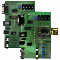
The Pixie Evaluation boards are supplied in sets of
two, one with a Pixie module mounted onboard, the
other with a Pixie Lite module mounted on-board.
The modules are preloaded with Pixie Switcher
firmware. This is simple switching firmware using the
ZigBee HC-L profile for turning things on and off. A
short tutorial is given on the next page. For detailed
instructions, please read the Pixie Switcher data
sheet. Contact us regarding the availability of other
firmware.
Power
Power may be provided from a 3-12 VDC supply
using
Alternatively, two AA batteries can be connected.
The cylindrical wall of the battery must be insulating
to be compatible with the metal battery clips supplied.
Jumper switches
Connect 1A-1B, 2A-2B, 3A-3B during normal use.
Remove them to program via the ICD2 connector.
4A-4B connects the RS232 driver to the Pixie RxD
input pin, allowing operation. Connect this jumper to
use the RS232 port, or remove it to use the Pixie
Config Tool connector. (Applies to revision ZEVr4
Page 2
ZEVr4 board shown
the
25-Jun-07
9A
2.5mm
7A
8B
A6 EP6
8A
center
Pixie Eval Kit DS482-11
A1 EP1
V
ModeA
ModeB
LED
6A 6B
positive
Gnd
A4 EP4
Status
A2 EP2
connector.
Gnd
Gnd
Gnd
SCL
SDI
RA0
RB4
RB5
RA4
RA1
RA2
RA3
RE2
© FlexiPanel Ltd
CTS
A5 EP5 RTS
Pixie
Pixie
Lite
or
Integral
antenna
RTS
CTS
boards and higher.
Revision ZEVr3 notes.)
Connect 5A-5B during normal use.
ammeter across these pins for current consumption
measurement.
Connect 6A-6B during normal use.
disconnect power from LEDs and trimmer for current
measurements.
Connect 8A-7A for an LED on the RA2 pin, or 8A-8B
for a trimmer, or 8A-9A for push switch.
Connect 10B-9B for RB5 to connect to CTS flow
control input, or 10B-10A for push switch.
Programming with ICD2
To program the Pixies using the ICD2 programmer /
debugger form Microchip Technology, connect the
ICD2 programmer using the RJ11 socket marked
ICD2. Jumper switches 1A-1B, 2A-2B, 3A-3B should
be removed while programming the Pixies.
Revision ZEVr3 notes
input from the RS232 line driver and the LED is
disconnected. To do this (irreversibly), use a sharp
knife to cut the track on the board underside
(1) Config tool port will be TxD only unless the RxD
NMCLR
Vunreg
SDO
Gnd
Gnd
Gnd
RE0
RB7
RB6
RE1
RxD
Vdd
TxD
RS232 line
Patents apply and/or pending
RS232
driver
socket
ICD2
2B
3B
1B 1A
Gnd
5B 5A
2A
3A
RxD
TxD
Power
For ZEVr3 boards, refer to
A7 EP7
Bind
Reset
A3 EP3
A6 EP8
Power
TxD
RxD
center positive
3-12V DC
www.FlexiPanel.com
3.3V reg
Gnd
4B
4A
Connect an
Remove to
Related parts for EVAL-PIXIE
Image
Part Number
Description
Manufacturer
Datasheet
Request
R

Part Number:
Description:
ENERCHIP CC EVAL KIT
Manufacturer:
Cymbet Corporation
Datasheet:

Part Number:
Description:
BOARD EVAL FOR AD976
Manufacturer:
Analog Devices Inc
Datasheet:

Part Number:
Description:
BOARD EVAL FOR ADXL345
Manufacturer:
Analog Devices Inc
Datasheet:

Part Number:
Description:
ENERCHIP CC SEH EVAL KIT
Manufacturer:
Cymbet Corporation
Datasheet:

Part Number:
Description:
ENERCHIP EP ENERGY HARVEST EVAL
Manufacturer:
Cymbet Corporation
Datasheet:

Part Number:
Description:
EVAL BOARD FOR TW6864-LB2-GR
Manufacturer:
Intersil
Datasheet:
Part Number:
Description:
EVAL BOARD FOR TW8816-LB3-GR
Manufacturer:
Intersil
Datasheet:
Part Number:
Description:
EVAL BOARD FOR TW8817-TA3-GRS
Manufacturer:
Intersil
Datasheet:

Part Number:
Description:
EVALUATION MODULE FOR ADUM4160
Manufacturer:
Analog Devices Inc
Datasheet:

Part Number:
Description:
BOARD EVALUATION ADCMP581BCP
Manufacturer:
Analog Devices Inc
Datasheet:
Part Number:
Description:
BOARD EVALUATION ADM1041
Manufacturer:
Analog Devices Inc
Datasheet:

Part Number:
Description:
EVAL BOARD FOR STM32F107VCT
Manufacturer:
STMicroelectronics
Datasheet:
Part Number:
Description:
BOARD EVAL FOR AD1954
Manufacturer:
Analog Devices Inc
Datasheet:
Part Number:
Description:
BOARD EVAL FOR AD1955
Manufacturer:
Analog Devices Inc
Datasheet:

Part Number:
Description:
BOARD EVAL FOR AD7655
Manufacturer:
Analog Devices Inc
Datasheet: