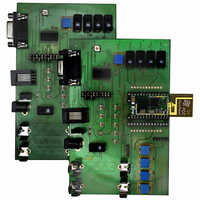
EVAL-PIXIE Flexipanel, EVAL-PIXIE Datasheet - Page 3

EVAL-PIXIE
Manufacturer Part Number
EVAL-PIXIE
Description
KIT EVALUATION PIXIE
Manufacturer
Flexipanel
Series
Pixie™r
Type
802.15.4/Zigbeer
Specifications of EVAL-PIXIE
Frequency
2.4GHz
Interface Type
RS-232
For Use With/related Products
Pixie ZigBee Modules
Lead Free Status / RoHS Status
Lead free / RoHS Compliant
Other names
658-1012
PIXIE-EVAL
ZEVR3
PIXIE-EVAL
ZEVR3
highlighted in black in the diagram below. Take care
not to cut any other tracks, not to short the track to
the ground plane, and not to damage the Pixie by
leaning the board on it.
RS232 line driver entirely – see note (2).
(2) RS232 driver is not powered down by removing
jumper 6A-6B.
measurement this component must be removed.
(The Config tool can still be used for serial
communications.)
Quick Start Guide – Switcher
The firmware loaded on the evaluation boards is
Pixie Switcher.
using the ZigBee HC-L profile for turning things on
and off. Contact us regarding the availability of other
firmware.
This documentation assumes the Switcher firmware
you have loaded is version 1.0-3.5-2.0. You can find
out which firmware you have loaded in step 6 of
tutorial 1.
The Pixie Evaluation Board (marked ZPCrX) is
loaded with ZigBee HC-L coordinator firmware. The
Pixie Lite evaluation board (ZPKrX) is loaded with
ZigBee HC-L sleepy end device firmware. You might
want to label them:
In the first tutorial you will set up endpoints for
switching between the coordinator and the sleepy
end device. You will need a PC and at least one
RS232 serial port, preferably two.
In the second tutorial you will set up failsafe alarm
which allows battery powered devices to confirm that
they are working correctly.
Page 3
Pixie Lite Board = Sleepy End Device
25-Jun-07
Pixie Board = Coordinator
This is simple switching firmware
For accurate power consumption
Pixie Eval Kit DS482-11
Alternatively, remove the
© FlexiPanel Ltd
In the third tutorial you will add an additional router
and end device.
reprogram the router for use as a sniffer so you can
watch messages being sent. To perform the third
and fourth tutorials you will need:
Tutorial 1 – ZigBee Switching Concepts
In this tutorial you will cover basic ZigBee concepts
such as joining and binding while setting up a
ZigBee switching system.
Configuring the boards
The purpose of configuring the board is to tell the
firmware what hardware is connected to it.
would usually be done at the OEM’s factory with the
use of a serial port or configuration tool.
1. Connect the serial port to the D9 socket on the
2. Set up a HyperTerminal session on the PC with
3. Connect the jumpers on the Coordinator as
4. Power up the Coordinator. Various LEDs may
5. If at step 4 you received the message
•
•
•
•
•
Coordinator.
the serial port set at 19200 baud, 8N1, no flow
control.
follows: 1A-1B, 2A-2B, 3A-3B, 5A-5B, 6A-6B, 8A-
8B, 10A-10B
turn on and initialization messages may appear
in the HyperTerminal window.
you must type in a MAC address. (If you don’t,
go to step 6.) For evaluation purposes, type in
any 10-hex-digit value in the range 3841000000
to 384100FFFF.
each device MUST be different! You will only
have to do this once after programming using the
ICD2.
A Pixie Switcher Firmware License. This is free
on application from FlexiPanel Ltd and enables
us to send you the switcher firmware hex files.
A second Pixie Evaluation Kit
An ICD2 programmer to program the Pixies.
This is available from Microchip Technology.
MPLAB PIC development environment software
for controlling the ICD2. This is a free download
from Microchip Technology.
Pixie Sniffer Development Kit. This is a free
download from FlexiPanel Ltd.
Patents apply and/or pending
MAC ->
In the fourth tutorial, you will
Note: the MAC address of
www.FlexiPanel.com
This


