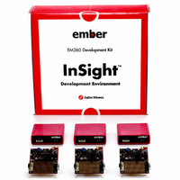
EM260-DEV Ember, EM260-DEV Datasheet - Page 88

EM260-DEV
Manufacturer Part Number
EM260-DEV
Description
KIT DEV FOR EM260
Manufacturer
Ember
Series
InSightr
Type
802.15.4/Zigbeer
Specifications of EM260-DEV
Frequency
2.4GHz
For Use With/related Products
EM260
Lead Free Status / RoHS Status
Contains lead / RoHS non-compliant
Other names
636-1005
- Current page: 88 of 94
- Download datasheet (738Kb)
EM260
8 Typical Application
88
120-1003-000D
Harmonic
C3
Filter
L2
C1
C2
Balun (BLN1)
Ceramic
Figure 12 illustrates the typical application circuit for the EM260. This figure does not contain all decoupling
capacitance required by the EM260. The Balun provides the impedance transformation from the antenna to
the EM250 for both TX and RX modes. The harmonic filter provides additional suppression of the second
harmonic, which increases the margin over the FCC limit. The 24MHz crystal with loading capacitors is re-
quired and provides the high frequency source for the EM250. The RC debounce filter (R4 and C7) is suggested
to improve the noise immunity of the RESET logic (Pin 11).
The SIF (nSIF_LOAD, SIF_MOSI, SIF_MISO, and SIF_CLK) and Packet Trace Signals (PTI_EN and PTI_TXD) should
be brought out test points or, if space permits to a 10-pin, dual row, 0.05-inch pitch header footprint. With a
header populated, a direct connection to the InSight Adapter is possible which enhances the debug capability
of the EM260. For more information, refer to the EM260 Reference Design.
1.8V
R1
L1
1.8V
RF_TX_ALT_N
RF_TX_ALT_P
VDD_PADSA
R2
TX_ACTIVE
VDD_VCO
VDD_RF
VDD_IF
BIAS_R
RF_P
RF_N
C4
R3
10
1
2
3
4
5
6
7
8
9
C6
40 39 38 37 36 35 34 33 32 31
11 12 13 14 15 16 17 18 19 20
X1
GND
41
EM260
C5
Figure 12. Typical Application Circuit
U1
Route to LED
or leave unconnected
30
29
28
27
26
25
24
23
22
21
(2.1V to 3.6V)
SIF_LOADB
SIF_MOSI
SIF_MISO
SIF_CLK
HOST_INT
RES
VDD_PADS
PTI_DATA
PTI_EN
SSEL
VDD_PADS
R4
C7
Programming and
Debug Interface (these
pins should be routed
to test points)
(2.1V to 3.6V)
VDD_PADS
Serial Interface
(route to Host uP)
Related parts for EM260-DEV
Image
Part Number
Description
Manufacturer
Datasheet
Request
R

Part Number:
Description:
IC ZIGBEE SYSTEM-ON-CHIP 40-QFN
Manufacturer:
Ember
Datasheet:

Part Number:
Description:
EM260 RCM BOARD
Manufacturer:
Ember
Datasheet:

Part Number:
Description:
EM260 BREAKOUT BOARD
Manufacturer:
Ember
Datasheet:

Part Number:
Description:
KIT JUMP START FOR EM260
Manufacturer:
Ember
Datasheet:

Part Number:
Description:
IC ZIGBEE SYSTEM-ON-CHIP 40-QFN
Manufacturer:
Ember
Datasheet:

Part Number:
Description:
KIT DEV EMBER ZIGBEE W/PCWH
Manufacturer:
Custom Computer Services Inc (CCS)

Part Number:
Description:
PROGRAMMER USB FLASH EM250/260
Manufacturer:
Ember
Datasheet:

Part Number:
Description:
IC ZIGBEE SYSTEM-ON-CHIP 48-QFN
Manufacturer:
Ember
Datasheet:

Part Number:
Description:
IC RF TXRX ZIGBEE 128KB 48QFN
Manufacturer:
Ember
Datasheet:

Part Number:
Description:
IC RF TXRX ZIGBEE 192KB 48QFN
Manufacturer:
Ember
Datasheet:

Part Number:
Description:
INSIGHT ADAPTER FOR EM2XX
Manufacturer:
Ember
Datasheet:

Part Number:
Description:
IAR EWARM LICENCE FOR EM35X
Manufacturer:
Ember
Datasheet:

Part Number:
Description:
KIT EVAL EM250 RF TEST
Manufacturer:
Ember
Datasheet:

Part Number:
Description:
INSIGHT ADAPTER 3 FOR EM35X
Manufacturer:
Ember
Datasheet:

Part Number:
Description:
EM250 RCM BOARD
Manufacturer:
Ember
Datasheet:


