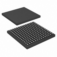
HSP50216KIZ Intersil, HSP50216KIZ Datasheet - Page 25

HSP50216KIZ
Manufacturer Part Number
HSP50216KIZ
Description
IC DOWNCONVERTER DGTL 4CH 196BGA
Manufacturer
Intersil
Datasheet
1.HSP50216KIZ.pdf
(58 pages)
Specifications of HSP50216KIZ
Function
Downconverter
Rf Type
W-CDMA
Package / Case
196-BGA
Lead Free Status / RoHS Status
Lead free / RoHS Compliant
The median mode minimizes the settling time. This mode
uses a fixed gain adjustment with only the direction of the
adjustment controlled by the gain error. This makes the
settling time independent of the signal level.
For example, if the loop is set to adjust 0.5dB per output
sample, the loop gain can slew up or down by 16dB in 16
symbol times, assuming a 2 samples per symbol output
sample rate. This is called a median settling mode because
the loop settles to where there is an equal number of
magnitude samples above and below the threshold. The
disadvantage of this mode is that the loop will have a wander
(dither) equal to the programmed step size. For this reason,
it is advisable to set one loop gain for fast settling at the
beginning of the burst and the second loop gain for small
adjustments during tracking.
In the median mode, the maximum gain step is
approximately 3dB/output. The step is fixed (it does not
decrease as the error decreases) so a large gain will cause
AM on the output at least that large. The gain should be
lowered after the settling. The fixed gain step is set by the
programmable AGC loop gain register IWA *010h.
For median mode, The AGC gain limits register sets the
minimum and maximum limits on the AGC gain. The total
AGC gain range is 96dB, but only a portion of the range
should be needed for most applications. For example, with a
16-bit output to a processor, the 16 bits may be sufficient for
all but 24dB of the total input range possible. The AGC
would only need to have a range of 24dB. This allows faster
settling and the AGC would be at its maximum gain limit
except when a high power signal was received. The AGC
may be disabled by setting both limits to the same value.
The median settling mode is enabled by setting IWA register
*013h bit 8 to 0 while the mean loop settling mode is
selected by setting bit 8 to 1.
Cartesian to Polar Converter
The Cartesian to Polar converter computes the magnitude
and phase of the I/Q vector. The I and Q inputs are 24 bits.
The converter phase output is 24 bits, MSB’s routed to the
output formatter and all 24 bits routed to the frequency
discriminator. The 24-bit output phase can be interpreted
either as two’s complement (-0.5 to approximately 0.5) or
unsigned (0.0 to approximately 1.0), as shown in Figure 2.
The phase conversion gain is 1/2π. The phase resolution is
24 bits. The 24-bit magnitude is unsigned binary format with
a range from 0 to 2.32. The magnitude conversion gain is
1.64676. The magnitude resolution is 24 bits. The MSB is
always zero.
Table 1 details the phase and magnitude weighting for the 16
bits output from the PDC.
25
HSP50216
The magnitude and phase computation requires 17 clocks
for full precision. At the end of the 17 clocks, the magnitude
and phase are latched into a register to be held for the next
stage, either the output formatter or frequency discriminator.
If a new input sample arrives before the end of the 17 cycles,
the results of the computations up until that time, are
latched. This latching means that an increase in speed
causes only a decrease in resolution. Table 2 details the
exact resolution that can be obtained with a fixed number of
clock cycles up to the required 17. The input magnitude and
phase errors induced by normal SNR values will almost
always be worse than the Cartesian to Polar conversion.
800000
FIGURE 2. PHASE BIT MAPPING OF COORDINATE
7fffff
±
π
23 (MSB)
0 (LSB)
BIT
22
21
20
19
18
17
16
15
14
13
12
10
11
400000
9
8
7
6
5
4
3
2
1
bfffff
TABLE 1. MAG/PHASE BIT WEIGHTING
CONVERTER OUTPUT
+
-
π/2
π/2
Q
c00000
3ff fff
I
000000
ffffff
0
MAGNITUDE
2
2
2
2
2
2
2
2
2
2
2
2
2
2
2
2
2
2
2
2
2
2
2
2
-10
-11
-12
-13
-14
-15
-16
-17
-18
-19
-20
-21
-1
-2
-3
-4
-5
-6
-7
-8
-9
2
1
0
800000
7fffff
π
400000
bfffff
180
90
45
22.5
11.25
5.625
2.8125
1.40625
0.703125
0.3515625
0.17578125
0.087890625
0.043945312
0.021972656
0.010986328
0.005483164
0.002741582
0.001370791
0.0006853955
0.00034269775
0.00017134887
0.00008567444
0.00004283722
0.00002141861
3π/2
π/2
PHASE (
c00000
Q
3fffff
August 17, 2007
I
000000
ffffff
o
FN4557.6
0
)


