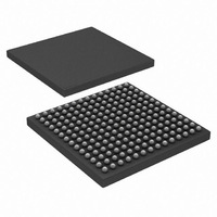
HSP50216KIZ Intersil, HSP50216KIZ Datasheet - Page 41

HSP50216KIZ
Manufacturer Part Number
HSP50216KIZ
Description
IC DOWNCONVERTER DGTL 4CH 196BGA
Manufacturer
Intersil
Datasheet
1.HSP50216KIZ.pdf
(58 pages)
Specifications of HSP50216KIZ
Function
Downconverter
Rf Type
W-CDMA
Package / Case
196-BGA
Lead Free Status / RoHS Status
Lead free / RoHS Compliant
P(31:0)
P(31:0)
P(31:0)
P(15:0)
31:0
31:0
31:0
These locations in RAM are used to store the Filter Compute Engine instruction words. There are 128 bits per instruction word with
each word consisting of condition code selects, FIR parameters and data routing controls. The filter compute engine is controlled by
a simple sequencer supporting up to 32 steps where each step is defined by a 128 bit instruction word. The 128 bit instruction word
is assigned to RAM memory in four 32 bit data writes through the Microprocessor Interface starting with the low 32 bits. Hence, 128
32-bit memory locations are required per channel to support the 32 steps of the Filter Sequencer. See the Filter Compute Engine and
Filter Sequencer sections of the data sheet for more details.
These locations in RAM are used to store the 22-bit filter coefficients used by the Filter Compute Engine of each channel in
implementing a FIR filter. The 22-bit FIR filter coefficients are loaded in the upper 22 bits of each 32-bit RAM location. The two LSBs
of the second byte (bits 9:8 of the total 32 bits, 31:0) are the shift bits. These are set to zero if not used. The least significant byte
(bits 7:0 of the total 32 bits, 31:0) are ignored. RAM1 address space allows for storage of 64 filter coefficients out of the total of 192
filter coefficient storage locations. See the Filter Compute Engine and Filter Sequencer sections of the data sheet for more details.
These locations in RAM are used to store the 22-bit filter coefficients used by the Filter Compute Engine of each channel in
implementing a FIR filter. The 22-bit FIR filter coefficients are loaded in the upper 22 bits of each 32-bit RAM location. The two LSBs
of the second byte (bits 9:8 of the total 32 bits, 31:0) are the shift bits. These are set to zero if not used. The least significant byte
(bits 7:0 of the total 32 bits, 31:0) are ignored.
filter coefficient storage locations. See the Filter Compute Engine and Filter Sequencer sections of the data sheet for more details.
TABLE 32. FILTER COMPUTE ENGINE INSTRUCTION POINTER RAMS (IWA = *180h THROUGH *1FCh)
TABLE 31. FILTER COMPUTE ENGINE INSTRUCTION RAMS (IWA = *100h THROUGH *17Fh)
TABLE 33. FILTER COMPUTE ENGINE COEFFICIENT RAM1 (IWA = *440h THROUGH *47Fh)
TABLE 34. FILTER COMPUTE ENGINE COEFFICIENT RAM2 (IWA = *480h THROUGH *4FFh)
41
RAM2
HSP50216
address space allows for storage of 128 filter coefficients out of the total of 192
FUNCTION
FUNCTION
FUNCTION
FUNCTION
August 17, 2007
FN4557.6


