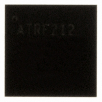
AT86RF212-ZU Atmel, AT86RF212-ZU Datasheet - Page 31

AT86RF212-ZU
Manufacturer Part Number
AT86RF212-ZU
Description
IC TXRX ZIGBE/802.15.4/ISM 32QFN
Manufacturer
Atmel
Datasheet
1.AT86RF212-ZU.pdf
(172 pages)
Specifications of AT86RF212-ZU
Frequency
700MHz, 800MHz, 900MHz
Data Rate - Maximum
250kbps
Modulation Or Protocol
802.15.4 Zigbee, 6LoWPAN, ISM
Applications
ISM, ZigBee™
Power - Output
10dBm
Sensitivity
-110dBm
Voltage - Supply
1.8 V ~ 3.6 V
Current - Receiving
9.2mA
Current - Transmitting
25mA
Data Interface
PCB, Surface Mount
Antenna Connector
PCB, Surface Mount
Operating Temperature
-40°C ~ 85°C
Package / Case
32-VQFN Exposed Pad, 32-HVQFN, 32-SQFN, 32-DHVQFN
Number Of Receivers
1
Number Of Transmitters
1
Wireless Frequency
769 MHz to 935 MHz
Interface Type
SPI
Noise Figure
7 dB
Output Power
21 dB
Operating Supply Voltage
1.8 V, 3 V
Maximum Operating Temperature
+ 85 C
Mounting Style
SMD/SMT
Maximum Supply Current
25 mA
Minimum Operating Temperature
- 40 C
Modulation
OQPSK
Protocol Supported
802.15.4
Operating Temperature (min)
-40C
Operating Temperature (max)
85C
Operating Temperature Classification
Industrial
Lead Free Status / RoHS Status
Lead free / RoHS Compliant
Memory Size
-
Lead Free Status / Rohs Status
Lead free / RoHS Compliant
Available stocks
Company
Part Number
Manufacturer
Quantity
Price
Company:
Part Number:
AT86RF212-ZU
Manufacturer:
HITTITE
Quantity:
5 000
Part Number:
AT86RF212-ZU
Manufacturer:
ATMEL/爱特梅尔
Quantity:
20 000
Part Number:
AT86RF212-ZUR
Manufacturer:
MICROCHIP/微芯
Quantity:
20 000
5.1.1 State Control
5.1.2 Description
5.1.2.1 P_ON – Power-on after V
8168C-MCU Wireless-02/10
DD
The radio transceiver states are controlled either by writing commands to register bits
TRX_CMD
pin 11 (SLP_TR) and pin 8 (/RST). A successful state change can be verified by
reading the radio transceiver status from register 0x01 (TRX_STATUS).
If TRX_STATUS = 0x1F (STATE_TRANSITION_IN_PROGRESS), the AT86RF212 is
in a state transition. Do not try to initiate a further state change while the radio
transceiver is in STATE_TRANSITION_IN_PROGRESS.
Pin SLP_TR is a multifunctional pin, refer to section 4.6. Depending on the radio
transceiver state, a rising edge of pin SLP_TR causes the following state transitions:
• TRX_OFF
• RX_ON
• PLL_ON
whereas the falling edge of pin SLP_TR causes the following state transitions:
• SLEEP
• RX_ON_NOCLK
Pin 8 (/RST) causes a reset of all registers (register bits CLKM_CTRL are shadowed;
for details, refer to section 7.7.4) and the content of the SRAM is deleted. It forces the
radio transceiver into TRX_OFF state. However, if the device was in P_ON state, it
remains in P_ON state.
For all states except SLEEP, the state change commands FORCE_TRX_OFF or
TRX_OFF lead to a transition into TRX_OFF state. If the radio transceiver is in active
receive or transmit states (BUSY_*), the command FORCE_TRX_OFF interrupts these
active processes and forces an immediate transition to TRX_OFF. By contrast, a
TRX_OFF command is stored until an active state (receiving or transmitting) has been
finished. After that the transition to TRX_OFF is performed.
For a fast transition from receive or active transmit states to PLL_ON state, the
command FORCE_PLL_ON is provided. Active processes are interrupted. In contrast
to FORCE_TRX_OFF, this command does not disable the PLL and the analog voltage
regulator AVREG. It is not available in states SLEEP, P_ON, RESET, and all *_NOCLK
states.
The completion of each requested state change shall always be confirmed by reading
the register bits TRX_STATUS (register 0x01, TRX_STATUS).
When the external supply voltage (V
transceiver goes into P_ON state performing an on-chip reset. The crystal oscillator is
activated and the default 1 MHz master clock is provided at pin 17 (CLKM) after the
crystal oscillator has stabilized. CLKM can be used as a clock source to the
microcontroller. The SPI interface and digital voltage regulator are enabled.
The on-chip power-on reset sets all registers to their default values. A dedicated reset
signal from the microcontroller at pin 8 (/RST) is not necessary but recommended for
hardware/software synchronization reasons.
All digital inputs have pull-up or pull-down resistors during P_ON state, refer to section
2.2.2.2. This is necessary to support microcontrollers where GPIO signals are floating
(register
0x02,
TRX_STATE),
→
→
→
→
→
DD
) is applied first to the AT86RF212, the radio
SLEEP
RX_ON_NOCLK
BUSY_TX
TRX_OFF
RX_ON
or
directly
by
AT86RF212
two
signal
pins:
31


