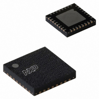
MFRC52301HN1,157 NXP Semiconductors, MFRC52301HN1,157 Datasheet - Page 61

MFRC52301HN1,157
Manufacturer Part Number
MFRC52301HN1,157
Description
IC READER 13.56MHZ 32-HVQFN
Manufacturer
NXP Semiconductors
Datasheet
1.MFRC52301HN1151.pdf
(97 pages)
Specifications of MFRC52301HN1,157
Frequency
13.56MHz
Package / Case
32-VQFN Exposed Pad, 32-HVQFN, 32-SQFN, 32-DHVQFN
Lead Free Status / RoHS Status
Lead free / RoHS Compliant
Features
-
Rf Type
-
Lead Free Status / RoHS Status
Lead free / RoHS Compliant
Other names
935282956157
- Current page: 61 of 97
- Download datasheet (3Mb)
NXP Semiconductors
MFRC523_34
Product data sheet
PUBLIC
9.2.4.3 TestSel2Reg register
9.2.4.4 TestPinEnReg register
General test signal configuration and PRBS control.
Table 120. TestSel2Reg register (address 32h); reset value: 00h bit allocation
Table 121. TestSel2Reg register bit descriptions
Enables the test bus pin output driver.
Table 122. TestPinEnReg register (address 33h); reset value: 80h bit allocation
Table 123. TestPinEnReg register bit descriptions
Bit
Symbol
Access
Bit
7
6
5
4 to 0 TestBusSel[4:0]
Bit
Symbol
Access
Bit
7
6 to 1 TestPinEn[5:0]
0
Symbol
TstBusFlip
PRBS9
PRBS15
Symbol
RS232LineEn
reserved
RS232LineEn
TstBusFlip
R/W
R/W
7
7
All information provided in this document is subject to legal disclaimers.
Rev. 3.5 — 24 September 2010
Value Description
0
-
-
PRBS9
R/W
Value Description
1
-
-
-
6
6
serial UART lines MX and DTRQ are disabled
enables the output driver on one of the data pins D1 to D7 which
outputs a test signal
Example:
Remark: If the SPI is used, only pins D1 to D4 can be used. If the
serial UART interface is used and the RS232LineEn bit is set to
logic 1 only pins D1 to D4 can be used.
reserved for future use
115235
test bus is mapped to the parallel port in the following order:
TstBusBit4,TstBusBit3, TstBusBit2, TstBusBit6, TstBusBit5,
TstBusBit0; see
starts and enables the PRBS9 sequence according to
ITU-TO150; the data transmission of the defined sequence is
started by the Transmit command
Remark: all relevant registers to transmit data must be
configured before entering PRBS9 mode
starts and enables the PRBS15 sequence according to
ITU-TO150; the data transmission of the defined sequence is
started by the Transmit command
Remark: all relevant registers to transmit data must be
configured before entering PRBS15 mode
selects the test bus; see
setting bit 1 to logic 1 enables pin D1 output
setting bit 5 to logic 1 enables pin D5 output
PRBS15
R/W
5
5
TestPinEn[5:0]
4
Section 16.1 on page 79
4
R/W
Section 16.1 “Test signals” on page 79
3
3
TestBusSel[4:0]
R/W
2
2
Contactless reader IC
MFRC523
© NXP B.V. 2010. All rights reserved.
1
1
reserved
61 of 97
0
0
-
Related parts for MFRC52301HN1,157
Image
Part Number
Description
Manufacturer
Datasheet
Request
R
Part Number:
Description:
Manufacturer:
NXP Semiconductors
Datasheet:
Part Number:
Description:
NXP Semiconductors designed the LPC2420/2460 microcontroller around a 16-bit/32-bitARM7TDMI-S CPU core with real-time debug interfaces that include both JTAG andembedded trace
Manufacturer:
NXP Semiconductors
Datasheet:

Part Number:
Description:
NXP Semiconductors designed the LPC2458 microcontroller around a 16-bit/32-bitARM7TDMI-S CPU core with real-time debug interfaces that include both JTAG andembedded trace
Manufacturer:
NXP Semiconductors
Datasheet:
Part Number:
Description:
NXP Semiconductors designed the LPC2468 microcontroller around a 16-bit/32-bitARM7TDMI-S CPU core with real-time debug interfaces that include both JTAG andembedded trace
Manufacturer:
NXP Semiconductors
Datasheet:
Part Number:
Description:
NXP Semiconductors designed the LPC2470 microcontroller, powered by theARM7TDMI-S core, to be a highly integrated microcontroller for a wide range ofapplications that require advanced communications and high quality graphic displays
Manufacturer:
NXP Semiconductors
Datasheet:
Part Number:
Description:
NXP Semiconductors designed the LPC2478 microcontroller, powered by theARM7TDMI-S core, to be a highly integrated microcontroller for a wide range ofapplications that require advanced communications and high quality graphic displays
Manufacturer:
NXP Semiconductors
Datasheet:
Part Number:
Description:
The Philips Semiconductors XA (eXtended Architecture) family of 16-bit single-chip microcontrollers is powerful enough to easily handle the requirements of high performance embedded applications, yet inexpensive enough to compete in the market for hi
Manufacturer:
NXP Semiconductors
Datasheet:
Part Number:
Description:
The XA-S3 device is a member of Philips Semiconductors? XA(eXtended Architecture) family of high performance 16-bitsingle-chip microcontrollers
Manufacturer:
NXP Semiconductors
Datasheet:

Part Number:
Description:
The NXP BlueStreak LH75401/LH75411 family consists of two low-cost 16/32-bit System-on-Chip (SoC) devices
Manufacturer:
NXP Semiconductors
Datasheet:

Part Number:
Description:
The NXP LPC3130/3131 combine an 180 MHz ARM926EJ-S CPU core, high-speed USB2
Manufacturer:
NXP Semiconductors
Datasheet:

Part Number:
Description:
The NXP LPC3141 combine a 270 MHz ARM926EJ-S CPU core, High-speed USB 2
Manufacturer:
NXP Semiconductors

Part Number:
Description:
The NXP LPC3143 combine a 270 MHz ARM926EJ-S CPU core, High-speed USB 2
Manufacturer:
NXP Semiconductors

Part Number:
Description:
The NXP LPC3152 combines an 180 MHz ARM926EJ-S CPU core, High-speed USB 2
Manufacturer:
NXP Semiconductors

Part Number:
Description:
The NXP LPC3154 combines an 180 MHz ARM926EJ-S CPU core, High-speed USB 2
Manufacturer:
NXP Semiconductors


