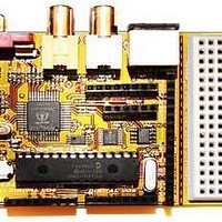
Chameleon-PIC Nurve Networks, Chameleon-PIC Datasheet - Page 38

Chameleon-PIC
Manufacturer Part Number
Chameleon-PIC
Description
MCU, MPU & DSP Development Tools PIC24 & PROPELLER DEV SYSTEM (SBC)
Manufacturer
Nurve Networks
Datasheet
1.CHAMELEON-PIC.pdf
(263 pages)
Specifications of Chameleon-PIC
Processor To Be Evaluated
PIC24
Data Bus Width
16 bit
Interface Type
USB, VGA, PS/2, I2C, ISP, SPI
Operating Supply Voltage
3.3 V, 5 V
Lead Free Status / RoHS Status
Lead free / RoHS Compliant
- Current page: 38 of 263
- Download datasheet (12Mb)
9.0 The SPI Bus and Communications System
The Chameleon uses SPI (serial peripheral interface) communications as the electrical communications interface to the
Propeller chip as well as the on board 1MB FLASH memory. The idea was we wanted to interface the PIC with both the
Propeller and the FLASH. The Propeller has no communications peripherals, so we could use anything we wanted; 2
lines, 4 lines, etc. and any kind of protocol we wished. However, since the FLASH memory was SPI, and there are 1000’s
of SPI devices out there, we decided to create a virtual SPI interface/driver for the Propeller and let it act as a SPI slave
device. With this design decision we can communicate with the Propeller, FLASH and any other external SPI devices all
with the PIC’s built in hardware (very fast) and we have a nice clean communications bus for everything. The only
challenge was supporting enough SPI devices, so the design uses a couple PIC I/O pins as chip selects for a multiplexer.
Referring to Figure 9.1, the idea is you place a 2-bit code on a pair of I/O pins (AIN1, AIN2) which are fed into a 74138
decoder, this gives us 4 active low chip select signals (SPI_SS0n…SPI_SS3n) which we can export out to 4 SPI devices
on the bus!
Referring to the schematic SPI_SS3n chip selects the FLASH. And if you look back a page or two at the Propeller
schematic on the left hand side locate the SPI signals, you will see that the Propeller uses SPI_SS2n as its chip select
respectively. The remaining chip selects (SPI_SS0n, SPI_SS1n) are exported out to the interface header J6 on pins (7,8)
respectively. So, you can hook up 2 more SPI devices easily with the MISO, MOSI, SCLK lines and then connect one of
the aforementioned SPI selects to enable it. All the other SPI devices will be disabled and thus no bus contingency issues.
10.0 VGA Graphics Hardware
In this chapter, we are going to take a look at the VGA hardware on the Chameleon PIC. The VGA hardware is very
simple consisting of little more than (8) I/O lines, and (3) D/A converters based on resistors. The Propeller chip does all
the work generating the VGA signal, but it’s nice to understand what’s going on, so we are going to briefly take a look at
the VGA specification, so you have a conversational understanding of it if you haven’t programmed direct VGA before and
why VGA is both good and bad from a video generation point of view. So, here’s what’s in store:
Origins of VGA.
Chameleon PIC VGA hardware design.
VGA signal primer.
Figure 9.1 – The SPI multiplexer design.
© 2009 NURVE NETWORKS LLC “Exploring the Chameleon PIC 16-Bit”
38
Related parts for Chameleon-PIC
Image
Part Number
Description
Manufacturer
Datasheet
Request
R

Part Number:
Description:
MCU, MPU & DSP Development Tools AVR8 VIDEO GAME DEV SYSTEM (SBC)
Manufacturer:
Nurve Networks

Part Number:
Description:
MCU, MPU & DSP Development Tools PIC24 VIDEO GAME DEV SYSTEM (SBC)
Manufacturer:
Nurve Networks

Part Number:
Description:
MCU, MPU & DSP Development Tools AVR8 & PROPELLER DEV SYSTEM (SBC)
Manufacturer:
Nurve Networks
Datasheet:


