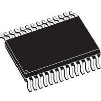
L6470H STMicroelectronics, L6470H Datasheet - Page 29

L6470H
Manufacturer Part Number
L6470H
Description
Motor / Motion / Ignition Controllers & Drivers 8 - 45V 7.0A 1/128 Microstepping SPI
Manufacturer
STMicroelectronics
Type
Micro Stepping Motor Driverr
Series
-r
Datasheet
1.EVAL6470.pdf
(64 pages)
Specifications of L6470H
Product
Stepper Motor Controllers / Drivers
Operating Supply Voltage
8 V to 45 V
Supply Current
0.5 mA
Mounting Style
SMD/SMT
Package / Case
HTSSOP-28
Operating Temperature
- 40 C to + 125 C
Applications
Stepper Motor Driver, 2 Phase
Evaluation Tools
*
Number Of Outputs
1
Current - Output
3A
Voltage - Load
8 V ~ 45 V
Voltage - Supply
3.3V, 5V
Mounting Type
*
Lead Free Status / RoHS Status
Lead free / RoHS Compliant
Available stocks
Company
Part Number
Manufacturer
Quantity
Price
Company:
Part Number:
L6470H
Manufacturer:
STMicroelectronics
Quantity:
135
Part Number:
L6470H
Manufacturer:
ST
Quantity:
20 000
Part Number:
L6470HTR
Manufacturer:
ST
Quantity:
20 000
L6470
6.17
6.17.1
6.17.2
6.18
BUSY\SYNC pin
This pin is an open drain output which can be used as busy or synchronization signal
according to SYNC_EN bit value (STEP_MODE register).
BUSY operation mode
The pin works as busy signal when SYNC_EN bit is set low (default condition). In this mode
the output is forced low while a constant speed, absolute positioning or motion command is
under execution. The BUSY pin is released when command has been executed (target
speed or target position reached). The STATUS register includes a BUSY flag that is the
BUSY pin mirror (see paragraph 9.1.22).
In case of daisy-chain configuration, BUSY pins of different ICs can be hard-wired to save
host controller GPIOs.
SYNC operation mode
The pin works as synchronization signal when SYNC_EN bit is set high. In this mode a step
clock signal is provided on output according to SYNC_SEL and STEP_SEL parameters
combination (see paragraph 9.1.19).
FLAG pin
By default an internal open drain transistor pulls the FLAG pin to ground when at least one
of the following conditions occurs:
●
●
●
●
●
●
●
●
●
●
It is possible to mask one or more alarm conditions by programming the ALARM_EN
register (see paragraph 9.1.20,
low, the alarm condition is masked and it does not cause a FLAG pin transition; all other
actions imposed by alarm conditions are performed anyway. In case of daisy-chain
configuration, FLAG pins of different ICs can be or-wired to save host controller GPIOs.
Power-up or standby/reset exit,
Stall detection on A bridge,
Stall detection on B bridge,
Overcurrent detection,
Thermal warning,
Thermal shutdown,
UVLO,
Switch turn-on event,
Wrong command,
Non performable command.
Doc ID 16737 Rev 2
Table
20). If the corresponding bit of ALARM_EN register is
Functional description
29/64


