LIS302DLH STMicroelectronics, LIS302DLH Datasheet - Page 20
LIS302DLH
Manufacturer Part Number
LIS302DLH
Description
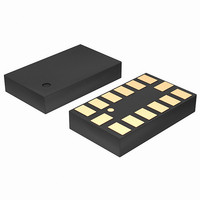
SENSOR ACCELEROMETER 3AXIS 14LGA
Manufacturer
STMicroelectronics
Datasheet
1.LIS302DLH.pdf
(37 pages)
Specifications of LIS302DLH
Featured Product
STM32 Cortex-M3 Companion Products
Axis
X, Y, Z
Acceleration Range
±2.3g, 9.2g
Sensitivity
18mg/digit, 72mg/digit
Voltage - Supply
2.16 V ~ 3.6 V
Output Type
Digital
Bandwidth
100Hz ~ 400Hz Selectable
Interface
I²C, SPI
Mounting Type
Surface Mount
Package / Case
14-LGA
Package Type
LGA
Operating Supply Voltage (min)
2.16V
Operating Supply Voltage (typ)
2.5V
Operating Supply Voltage (max)
3.6V
Operating Temperature (min)
-40C
Operating Temperature (max)
85C
Operating Temperature Classification
Industrial
Product Depth (mm)
3mm
Product Height (mm)
0.92mm
Product Length (mm)
5mm
Mounting
Surface Mount
Pin Count
14
Sensing Axis
Triple
Acceleration
2 g, 4 g, 8 g
Digital Output - Number Of Bits
16 bit
Supply Voltage (max)
3.6 V
Supply Voltage (min)
2.16 V
Maximum Operating Temperature
+ 85 C
Minimum Operating Temperature
- 40 C
Digital Output - Bus Interface
I2C, SPI
Lead Free Status / RoHS Status
Lead free / RoHS Compliant
Other names
497-10052
Available stocks
Company
Part Number
Manufacturer
Quantity
Price
Company:

Part Number:
LIS302DLHS0.5
Manufacturer:
INNOLUX
Quantity:
1 000
Company:
Part Number:
LIS302DLHTR
Manufacturer:
SANYO
Quantity:
11


Digital interfaces
5.2.1
20/37
Figure 6.
CS is the serial port enable and it is controlled by the SPI master. It goes low at the start of
the transmission and goes back high at the end. SPC is the serial port clock and it is
controlled by the SPI master. It is stopped high when CS is high (no transmission). SDI and
SDO are respectively the serial port data input and output. Those lines are driven at the
falling edge of SPC and should be captured at the rising edge of SPC.
Both the read register and write register commands are completed in 16 clock pulses or in
multiple of 8 in case of multiple bytes read/write. Bit duration is the time between two falling
edges of SPC. The first bit (bit 0) starts at the first falling edge of SPC after the falling edge
of CS while the last bit (bit 15, bit 23, ...) starts at the last falling edge of SPC just before the
rising edge of CS.
bit 0: RW bit. When 0, the data DI(7:0) is written into the device. When 1, the data DO(7:0)
from the device is read. In latter case, the chip will drive SDO at the start of bit 8.
bit 1: MS bit. When 0, the address will remain unchanged in multiple read/write commands.
When 1, the address is auto incremented in multiple read/write commands.
bit 2-7: address AD(5:0). This is the address field of the indexed register.
bit 8-15: data DI(7:0) (write mode). This is the data that is written into the device (MSb first).
bit 8-15: data DO(7:0) (read mode). This is the data that is read from the device (MSb first).
In multiple read/write commands further blocks of 8 clock periods will be added. When MS
bit is ‘0’ the address used to read/write data remains the same for every block. When MS bit
is ‘1’ the address used to read/write data is increased at every block.
The function and the behavior of SDI and SDO remain unchanged.
SPI read
Figure 7.
SDO
SPC
SDI
CS
SDO
SPC
Read and write protocol
SPI read protocol
SDI
CS
RW
MS
RW
AD5 AD4 AD3 AD2 AD1 AD0
MS
AD5 AD4 AD3 AD2 AD1 AD0
Doc ID 15797 Rev 1
DO7 DO6 DO5 DO4 DO3 DO2 DO1 DO0
DI7 DI6 DI5 DI4 DI3 DI2 DI1 DI0
DO7 DO6 DO5 DO4 DO3 DO2 DO1 DO0
LIS302DLH
Related parts for LIS302DLH
Image
Part Number
Description
Manufacturer
Datasheet
Request
R

Part Number:
Description:
STMicroelectronics [RIPPLE-CARRY BINARY COUNTER/DIVIDERS]
Manufacturer:
STMicroelectronics
Datasheet:
Part Number:
Description:
STMicroelectronics [LIQUID-CRYSTAL DISPLAY DRIVERS]
Manufacturer:
STMicroelectronics
Datasheet:

Part Number:
Description:
BOARD EVAL FOR MEMS SENSORS
Manufacturer:
STMicroelectronics
Datasheet:
Part Number:
Description:
NPN TRANSISTOR POWER MODULE
Manufacturer:
STMicroelectronics
Datasheet:
Part Number:
Description:
TURBOSWITCH ULTRA-FAST HIGH VOLTAGE DIODE
Manufacturer:
STMicroelectronics
Datasheet:
Part Number:
Description:
Manufacturer:
STMicroelectronics
Datasheet:
Part Number:
Description:
DIODE / SCR MODULE
Manufacturer:
STMicroelectronics
Datasheet:
Part Number:
Description:
DIODE / SCR MODULE
Manufacturer:
STMicroelectronics
Datasheet:
Part Number:
Description:
Search -----> STE16N100
Manufacturer:
STMicroelectronics
Datasheet:
Part Number:
Description:
Search ---> STE53NA50
Manufacturer:
STMicroelectronics
Datasheet:
Part Number:
Description:
NPN Transistor Power Module
Manufacturer:
STMicroelectronics
Datasheet:
Part Number:
Description:
DIODE / SCR MODULE
Manufacturer:
STMicroelectronics
Datasheet: