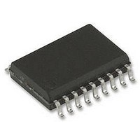
ST62T15CM6 STMicroelectronics, ST62T15CM6 Datasheet - Page 48

ST62T15CM6
Manufacturer Part Number
ST62T15CM6
Description
8BIT MCU OTP 2K, SMD, 62T15, SOIC20
Manufacturer
STMicroelectronics
Datasheet
1.ST62T15CB6.pdf
(105 pages)
Specifications of ST62T15CM6
Controller Family/series
ST6
Core Size
8bit
No. Of I/o's
20
Program Memory Size
2KB
Ram Memory Size
64Byte
Cpu Speed
8MHz
Oscillator Type
External Only
No. Of Timers
1
Digital Ic Case
RoHS Compliant
Peripherals
ADC,
Rohs Compliant
No
Processor Series
ST62T1x
Core
ST6
Data Bus Width
8 bit
Program Memory Type
EPROM
Data Ram Size
64 B
Maximum Clock Frequency
8 MHz
Number Of Programmable I/os
20
Number Of Timers
2
Operating Supply Voltage
3 V to 6 V
Maximum Operating Temperature
+ 85 C
Mounting Style
SMD/SMT
Package / Case
SOP-28
Development Tools By Supplier
ST62GP-EMU2, ST62E2XC-EPB/110, ST62E6XC-EPB/US, STREALIZER-II
Minimum Operating Temperature
- 40 C
On-chip Adc
8 bit
Lead Free Status / Rohs Status
In Transition
Available stocks
Company
Part Number
Manufacturer
Quantity
Price
Company:
Part Number:
ST62T15CM6
Manufacturer:
STM
Quantity:
2 508
Part Number:
ST62T15CM6
Manufacturer:
ST
Quantity:
20 000
ST6215C/ST6225C
8-BIT TIMER (Cont’d)
9.2.3 Counter/Prescaler Description
Prescaler
The prescaler input can be the internal frequency
f
the TIMER pin. The prescaler decrements on the
rising edge, depending on the division factor pro-
grammed by the PS[2:0] bits in the TSCR register.
The state of the 7-bit prescaler can be read in the
PSCR register.
When the prescaler reaches 0, it is automatically
reloaded with 7Fh.
Counter
The free running 8-bit downcounter is fed by the
output of the programmable prescaler, and is dec-
remented on every rising edge of the f
clock signal coming from the prescaler.
It is possible to read or write the contents of the
counter on the fly, by reading or writing the timer
counter register (TCR).
When the downcounter reaches 0, it is automati-
cally reloaded with the value 0FFh.
Counter Clock and Prescaler
The counter clock frequency is given by:
where f
The timer input clock feeds the 7-bit programma-
ble prescaler. The prescaler output can be pro-
grammed by selecting one of the 8 available pres-
caler taps using the PS[2:0] bits in the Status/Con-
trol Register (TSCR). Thus the division factor of
the prescaler can be set to 2
7). See
The clock input is enabled by the PSI (Prescaler
Initialize) bit in the TSCR register. When PSI is re-
set, the counter is frozen and the prescaler is load-
ed with the value 7Fh. When PSI is set, the pres-
48/105
1
INT
– f
– f
– f
divided by 12 or an external clock applied to
INT
EXT
INT
PRESCALER
/12
/12 gated by TIMER pin
Figure
f
(input on TIMER pin)
COUNTER
27.
= f
can be:
PRESCALER
n
(where n equals 0, to
/ 2
PS[2:0]
COUNTER
caler and the counter run at the rate of the select-
ed clock source.
Counter and Prescaler Initialization
After RESET, the counter and the prescaler are in-
itialized to 0FFh and 7Fh respectively.
The 7-bit prescaler can be initialized to 7Fh by
clearing the PSI bit. Direct write access to the
prescaler is also possible when PSI =1. Then, any
value between 0 and 7Fh can be loaded into it.
The 8-bit counter can be initialized separately by
writing to the TCR register.
9.2.3.1 8-bit Counting and Interrupt Capability
on Counter Underflow
Whatever the division factor defined for the pres-
caler, the Timer Counter works as an 8-bit down-
counter. The input clock frequency is user selecta-
ble using the PS[2:0] bits.
When the downcounter decrements to zero, the
TMZ (Timer Zero) bit in the TSCR is set. If the ETI
(Enable Timer Interrupt) bit in the TSCR is also
set, an interrupt request is generated.
The Timer interrupt can be used to exit the MCU
from WAIT or STOP mode.
The TCR can be written at any time by software to
define a time period ending with an underflow
event, and therefore manage delay or timer func-
tions.
TMZ is set when the downcounter reaches zero;
however, it may also be set by writing 00h in the
TCR register or by setting bit 7 of the TSCR register.
The TMZ bit must be cleared by user software
when servicing the timer interrupt to avoid unde-
sired interrupts when leaving the interrupt service
routine.
Note: A write to the TCR register will predominate
over the 8-bit counter decrement to 00h function,
i.e. if a write and a TCR register decrement to 00h
occur simultaneously, the write will take prece-
dence, and the TMZ bit is not set until the 8-bit
counter underflows again.


