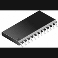
CS5524-AS Cirrus Logic Inc, CS5524-AS Datasheet - Page 4

CS5524-AS
Manufacturer Part Number
CS5524-AS
Description
A/D Converter (A-D) IC
Manufacturer
Cirrus Logic Inc
Datasheet
1.CS5524-AS.pdf
(56 pages)
Specifications of CS5524-AS
Sample Rate
606SPS
Input Channels Per Adc
4
Mounting Type
Surface Mount
No. Of Channels
4
Power Rating
9mW
Peak Reflow Compatible (260 C)
No
Supply Voltage Max
5.25V
Lead Free Status / RoHS Status
Contains lead / RoHS non-compliant
Available stocks
Company
Part Number
Manufacturer
Quantity
Price
Part Number:
CS5524-ASZ
Manufacturer:
CIRRUS
Quantity:
20 000
LIST OF FIGURES
LIST OF TABLES
4
Figure 1. Continuous Running SCLK Timing (Not to Scale) ......................................................... 12
Figure 2. SDI Write Timing (Not to Scale) ..................................................................................... 12
Figure 3. SDO Read Timing (Not to Scale) ................................................................................... 12
Figure 4. Multiplexer Configurations.............................................................................................. 13
Figure 5. Input Models for AIN+ and AIN- pins, £(100 mV Input Ranges...................................... 14
Figure 6. Input Models for AIN+ and AIN- pins, >100 mV input ranges ........................................ 14
Figure 7. Input Ranges Greater than 5 V ...................................................................................... 16
Figure 8. Input Model for VREF+ and VREF- Pins........................................................................ 16
Figure 9. CS5523/24 Register Diagram ........................................................................................ 17
Figure 10. Command and Data Word Timing................................................................................ 25
Figure 11. Self Calibration of Offset (Low Ranges)....................................................................... 32
Figure 12. Self Calibration of Offset (High Ranges) ...................................................................... 32
Figure 13. Self Calibration of Gain (All Ranges) ........................................................................... 32
Figure 14. System Calibration of Offset (Low Ranges) ................................................................. 32
Figure 15. System Calibration of Offset (High Ranges) ................................................................ 33
Figure 16. System Calibration of Gain (Low Ranges) ................................................................... 33
Figure 17. System Calibration of Gain (High Ranges) .................................................................. 33
Figure 18. Filter Response (Normalized to Output Word Rate = 1) .............................................. 42
Figure 19. Typical Linearity Error for CS5521/23 .......................................................................... 42
Figure 20. Typical Linearity Error for CS5522/24/28 ..................................................................... 42
Figure 21. CS5522 Configured to use on-chip charge pump to supply NBV ................................ 43
Figure 22. CS5522 Configured for ground-referenced Unipolar Signals....................................... 44
Figure 23. CS5522 Configured for Single Supply Bridge Measurement ....................................... 44
Figure 24. Charge Pump Drive Circuit for VD+ = 3 V.................................................................... 45
Figure 25. Alternate NBV Circuits ................................................................................................. 45
Table 1. Relationship between Full Scale Input, Gain Factors, and Internal Analog
Table 2. Command Register Quick Reference.............................................................................. 19
Table 3. Channel-Setup Registers ................................................................................................ 27
Table 4. Configuration Register..................................................................................................... 30
Table 5. Offset and Gain Registers ............................................................................................... 31
Table 6. Output Coding for 16-bit CS5521/23 and 24-bit CS5522/24/28 ...................................... 40
Signal Limitations ............................................................................................................. 15
CS5521/22/23/24/28
DS317F2


