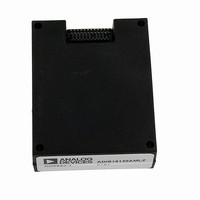
ADIS16130AMLZ Analog Devices Inc, ADIS16130AMLZ Datasheet - Page 12

ADIS16130AMLZ
Manufacturer Part Number
ADIS16130AMLZ
Description
MODULE GYRO RATE SENSOR 24LD
Manufacturer
Analog Devices Inc
Datasheet
1.ADIS16130AMLZ.pdf
(16 pages)
Specifications of ADIS16130AMLZ
Range °/s
±250°/s
Sensitivity
23,488LSB/°/s
Typical Bandwidth
300Hz
Voltage - Supply
4.75 V ~ 5.25 V
Current - Supply
73mA
Output Type
Digital
Operating Temperature
-40°C ~ 85°C
Package / Case
Module
No. Of Axes
1
Sensor Case Style
ML-24-3
No. Of Pins
24
Supply Voltage Range
4.75V To 5.25V
Operating Temperature Range
-40°C To +85°C
Msl
MSL 1 - Unlimited
Acceleration Range
2000g
Lead Free Status / RoHS Status
Lead free / RoHS Compliant
Lead Free Status / RoHS Status
Lead free / RoHS Compliant, Lead free / RoHS Compliant
Available stocks
Company
Part Number
Manufacturer
Quantity
Price
Company:
Part Number:
ADIS16130AMLZ
Manufacturer:
SENSIRIO
Quantity:
10 000
ADIS16130
APPLICATIONS INFORMATION
ACHIEVING OPTIMAL NOISE PERFORMANCE
Several system-level considerations can have an impact on the
noise and accuracy of the ADIS16130. Understanding and
managing these factors can influence the behavior of any high
performance system.
Supply and Common Considerations
The ADIS16130 provides approximately 1.8 μF of decoupling
capacitance. This capacitance is distributed throughout the
device and should be taken into account when considering
potential noise threats on the power supply lines.
Bandwidth Setting
If C
response, it should be placed close to the device. Long cable
leads and PCB traces increase the risk of introducing noise into
the system.
SECOND-LEVEL ASSEMBLY
The ADIS16130 package supports two mounting approaches:
a bulkhead mount, where the interface is separate from the
attachment surface, and a PCB mount that provides the
mechanical and electrical connections on the same surface.
Figure 16 provides a suggested design for the ADIS16130’s
mechanical attachment. The hole pattern shown in Figure 16
can support either mounting approach and enables the integration
of the mating socket layout that is illustrated in Figure 17.
The mating socket layout uses the Samtec CLM-112-02 family of
connectors. The 24 holes that are inside the pad accommodate the
pins on the ADIS16130, which can extend beyond the package
body. The stress relief provided by these holes is important for
maintaining reliability and optimal bias stability performance.
OUT
is applied to reduce the bandwidth of the ADIS16130
Rev. B | Page 12 of 16
0.054 [1.37]
39.60 BSC
0.022±
NONPLATED
THRU HOLE 2×
0.019685
[0.5000]
(TYP)
19.800 BSC
4x 2.500 BSC
Figure 17. Mating Socket Recommended Pad Layout with
DIA (TYP)
15.600 BSC
Figure 16. Suggested Hole Pattern for Mounting
17.520
Dimensions Shown in Inches and (Millimeters)
2.280
0.022 DIA THRU HOLE (TYP)
NONPLATED THRU HOLE
5.00 BSC
0.4334 [11.0]
31.200 BSC
5.00 BSC
FOR MATING SOCKET
ALIGNMENT HOLES
0.0394 [1.00]
0.0240 [0.610]
2x
0.0394 [1.00]
0.560 BSC
0.1800
[4.57]


