TCS10DLU(TE85L,F) Toshiba, TCS10DLU(TE85L,F) Datasheet
TCS10DLU(TE85L,F)
Specifications of TCS10DLU(TE85L,F)


Related parts for TCS10DLU(TE85L,F)

TCS10DLU(TE85L,F) Summary of contents
Page 1
... TOSHIBA CMOS Digital Integrated Circuit Silicon Monolithic Digital-Output Magnetic Sensor Feature Open-Drain Output South-Pole or North-Pole Detection Marking LA3 TCS10DLU Weight: 7.0 mg (typ.) Pin Assignment (top view) GND2 (Note 2) V (Note1 GND1 NC OUT (Note 2) Note 1: A 0.47μF capacitor should be connected near the device. This condition will not guarantee successful operation ...
Page 2
... Please design the appropriate reliability upon reviewing the Toshiba Semiconductor Reliability Handbook (“Handling Precautions”/“Derating Concept and Methods”) and individual reliability data (i.e. reliability test report and estimated failure rate, etc) ...
Page 3
DC Characteristics (Ta = 25°C) Characteristics Output Voltage Low- Level Output Leakage Current Average Current Supply Current Operating Current Operating Frequency Note 5: Supply Current is pulsed periodically by internal circuit. Magnetic Characteristics Characteristics Operating Point Magnetic Flux Releasing Point ...
Page 4
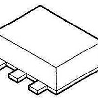
Package Dimensions Weight: 7.0 mg (typ.) 4 TCS10DLU 2011-02-07 ...
Page 5
Layout of Magnetic Detection Part Sensor Element Note: Dimensional tolerances are ± 0.1mm, unless otherwise specified. 0.85 Sensor Element (0.2 mm 1.05 0.3 5 TCS10DLU Unit 2011-02-07 ...
Page 6
... Product shall not be used for or incorporated into any products or systems whose manufacture, use, or sale is prohibited under any applicable laws or regulations. • The information contained herein is presented only as guidance for Product use. No responsibility is assumed by TOSHIBA for any infringement of patents or any other intellectual property rights of third parties that may result from the use of Product. No license to any intellectual property right is granted by this document, whether express or implied, by estoppel or otherwise. • ...