FX1S-30MR-ES/UL MITSUBISHI, FX1S-30MR-ES/UL Datasheet - Page 31
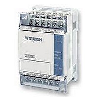
FX1S-30MR-ES/UL
Manufacturer Part Number
FX1S-30MR-ES/UL
Description
PLC, 16 IN, 14 RELAY OUT, 110V/2
Manufacturer
MITSUBISHI
Datasheet
1.FX1S-30MR-ESUL.pdf
(380 pages)
Specifications of FX1S-30MR-ES/UL
No. Of Analogue Inputs
16
No. Of Analogue Outputs
14
Ip/nema Rating
IP10
Approval Bodies
CE, CUL, UL
External Depth
49mm
External Length / Height
90mm
External Width
60mm
Mounting Type
Panel


2.5.2
FX Series Programmable Controllers
Double Coil Designation
If this is NOT ON then the second Y3 coil does NOT activate. Therefore the status of the Y3
coil updates to reflect this new situation, i.e. it turns OFF. The final outputs are then Y3 = OFF
and Y4 = ON.
: Input ON state NOT recognized
: Input ON state recognized
: Input OFF state NOT recognized
: 1 program processing
: Input processing
: Output processing
: A full program scan/operation cycle
Use of dual coils:
The last coil effect:
X1
Y3
X2
• Always check programs for incidents of dual coiling. If there are dual coils the
• In a dual coil designation, the coil operation designated last is the effective coil. That
1
program will not operate as expected - possibly resulting in physical damage.
is, it is the status of the previous coil that dictates the behavior at the current point in
the program.
5
6
4
t secs
2.
1.
4
7
Y3
Y4
Y3
2
3
Double or dual coiling is not a recommended
practice. Using multiple output coils of the
s a m e d e v i c e c a n c a u s e t h e p r o g r a m
operation to become unreliable. The example
program shown opposite identifies a double
coil situation; there are two Y3 outputs. The
following sequence of events will occur when
inputs X1 = ON and X2 = OFF;
1.The first Y3 tuns ON because X1 is ON. The
contacts associated with Y3 also energize
when the coil of output Y3 energizes. Hence,
output Y4 turns ON.
2.The last and most important line in this
program looks at the status of input X2.
handle such high speed input requests.
Input durations:
The ON or OFF duration of the PLC inputs
must be longer than the operation cycle
time of the PLC.
Taking a 10 msec (standard input filter)
response delay into account, the ON/OFF
duration must be longer than 20 msec if
the operation cycle (scan time) is 10 msec.
Therefore, in this example, input pulses of
more than 25Hz (1sec/(20msec ON +
20msec OFF)) cannot be sensed.
There are applied instructions provided to
Basic Program Instructions 2
2-5
Related parts for FX1S-30MR-ES/UL
Image
Part Number
Description
Manufacturer
Datasheet
Request
R

Part Number:
Description:
MITSUBISHI IGBT MODULES
Manufacturer:
MITSUBISHI
Datasheet:
Part Number:
Description:
MITSUBISHI INTELLIGENT POWER MODULES
Manufacturer:
MITSUBISHI
Datasheet:
Part Number:
Description:
TRANSFER-MOLD TYPE INSULATED TYPE
Manufacturer:
MITSUBISHI
Datasheet:
Part Number:
Description:
Manufacturer:
MITSUBISHI
Datasheet:
Part Number:
Description:
30A intelligent power module for flat-base type
Manufacturer:
MITSUBISHI
Datasheet:
Part Number:
Description:
15A - transistor module for medium power switching use, insulated type
Manufacturer:
MITSUBISHI
Datasheet:
Part Number:
Description:
5A power module for transfer-mold type insulated type
Manufacturer:
MITSUBISHI
Datasheet:
Part Number:
Description:
30A intelligent power module for flat-base type
Manufacturer:
MITSUBISHI
Datasheet:
Part Number:
Description:
TRANSFER-MOLD TYPE INSULATED TYPE
Manufacturer:
MITSUBISHI
Datasheet:
Part Number:
Description:
TRANSFER-MOLD TYPE INSULATED TYPE
Manufacturer:
MITSUBISHI
Datasheet:
Part Number:
Description:
20A - transistor module for medium power switching use, insulated type
Manufacturer:
MITSUBISHI
Datasheet:
Part Number:
Description:
20A - transistor module for medium power switching use, insulated type
Manufacturer:
MITSUBISHI
Datasheet: