FX1S-30MR-ES/UL MITSUBISHI, FX1S-30MR-ES/UL Datasheet - Page 34
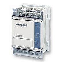
FX1S-30MR-ES/UL
Manufacturer Part Number
FX1S-30MR-ES/UL
Description
PLC, 16 IN, 14 RELAY OUT, 110V/2
Manufacturer
MITSUBISHI
Datasheet
1.FX1S-30MR-ESUL.pdf
(380 pages)
Specifications of FX1S-30MR-ES/UL
No. Of Analogue Inputs
16
No. Of Analogue Outputs
14
Ip/nema Rating
IP10
Approval Bodies
CE, CUL, UL
External Depth
49mm
External Length / Height
90mm
External Width
60mm
Mounting Type
Panel


2.8
FX Series Programmable Controllers
Load Pulse, Load Trailing Pulse
Program example:
Basic points to remember:
LDP
(LoaDPulse)
LDF
(LoaD Falling
pulse)
- Connect the LDP and LDF instructions directly to the left hand bus bar.
- Or use LDP and LDF instructions to define a new block of program when using the ORB
- LDP is active for one program scan after the associated device switches from OFF to ON.
- LDF is active for one program scan after the associated device switches from ON to
Single Operation flags M2800 to M3071:
Mnemonic
and ANB instructions (see later sections).
OFF.
• This is useful for use in STL programs (see chapter 3) to perform single step
• Any other instructions (LD, AND, OR, etc.) will operate as expected.
• The pulse operation instructions, when used with auxiliary relays M2800 to M3071,
For more details please see page 4-5.
only activate the first instruction encountered in the program scan, after the point in
the program where the device changes. Any other pulse operation instructions will
remain inactive.
operation using a single device.
X0
X0
X1
Initial logical
operation -
Rising edge
pulse
Initial logical
operation Falling
/ trailing edge
pulse
LDF
LDP
Function
M100
Format
Y0
X, Y, M, S, T, C
X, Y, M, S, T, C
Devices
0
2
3
4
6
Basic Program Instructions 2
LDP
OR
OUT
LDF
OUT
Program steps
X
X
M 100
X
Y
2-8
0
1
0
0
2
2
Related parts for FX1S-30MR-ES/UL
Image
Part Number
Description
Manufacturer
Datasheet
Request
R

Part Number:
Description:
MITSUBISHI IGBT MODULES
Manufacturer:
MITSUBISHI
Datasheet:
Part Number:
Description:
MITSUBISHI INTELLIGENT POWER MODULES
Manufacturer:
MITSUBISHI
Datasheet:
Part Number:
Description:
TRANSFER-MOLD TYPE INSULATED TYPE
Manufacturer:
MITSUBISHI
Datasheet:
Part Number:
Description:
Manufacturer:
MITSUBISHI
Datasheet:
Part Number:
Description:
30A intelligent power module for flat-base type
Manufacturer:
MITSUBISHI
Datasheet:
Part Number:
Description:
15A - transistor module for medium power switching use, insulated type
Manufacturer:
MITSUBISHI
Datasheet:
Part Number:
Description:
5A power module for transfer-mold type insulated type
Manufacturer:
MITSUBISHI
Datasheet:
Part Number:
Description:
30A intelligent power module for flat-base type
Manufacturer:
MITSUBISHI
Datasheet:
Part Number:
Description:
TRANSFER-MOLD TYPE INSULATED TYPE
Manufacturer:
MITSUBISHI
Datasheet:
Part Number:
Description:
TRANSFER-MOLD TYPE INSULATED TYPE
Manufacturer:
MITSUBISHI
Datasheet:
Part Number:
Description:
20A - transistor module for medium power switching use, insulated type
Manufacturer:
MITSUBISHI
Datasheet:
Part Number:
Description:
20A - transistor module for medium power switching use, insulated type
Manufacturer:
MITSUBISHI
Datasheet: