FX1S-30MR-ES/UL MITSUBISHI, FX1S-30MR-ES/UL Datasheet - Page 334
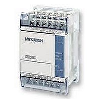
FX1S-30MR-ES/UL
Manufacturer Part Number
FX1S-30MR-ES/UL
Description
PLC, 16 IN, 14 RELAY OUT, 110V/2
Manufacturer
MITSUBISHI
Datasheet
1.FX1S-30MR-ESUL.pdf
(380 pages)
Specifications of FX1S-30MR-ES/UL
No. Of Analogue Inputs
16
No. Of Analogue Outputs
14
Ip/nema Rating
IP10
Approval Bodies
CE, CUL, UL
External Depth
49mm
External Length / Height
90mm
External Width
60mm
Mounting Type
Panel


10.3
10.3.1
FX Series Programmable Controllers
Using The Forced RUN/STOP Flags
A RUN/STOP push button configuration
The FX programmable controller has a single RUN terminal. When power is applied to this
terminal the PLC changes into a RUN state, i.e. the program contained is executed.
Consequently when there is no power ’on’ the RUN terminal the PLC is in a STOP state.
This feature can be utilized to provide the FX PLC with an external RUN/STOP - push button
control. The following PLC wiring and program addition are required.
Explanation:
Pressing the RUN push button sets the PLC into the RUN state. This means M8000 is ON.
Following the program, M8000 activates both M8035 and M8036. These two special auxiliary
devices set the PLC in to forced RUN mode. Releasing the RUN push button would normally
return the PLC to the STOP state, but because the two auxiliary coils, M8035 and 36 are ON,
the PLC remains in RUN. To stop the, PLC pressing the STOP push button drives an input ON
and consequently M8037 turns ON. This then automatically forces OFF both M8035 and 36
and resets itself. Hence, the PLC is in its STOP status and awaits the cycle to begin again.
Input priority:
• The STOP input is only processed after the programs END statement has been reached -
• To give priority to the STOP input and provide a 'safer' system, some form of mechanical/
• For push-button control to operate correctly, the user must set the RUN/STOP switch on
• FX
this is because the physical input used, i.e. an X device is normally updated and processed
at that time. Therefor, the RUN input is given priority when both RUN and STOP inputs are
given simultaneously.
circuitry interlock should be constructed between both RUN and STOP inputs. A very
simple example is shown in the wiring diagram above.
FX
for FX
settings.
2N
2N
and FX
and FX
2N
-16M) on the MPU should be configured as a RUN terminal in the parameter
2NC
2NC
units to the STOP position.
units do not have a RUN terminal. One of the inputs X0 to X17 (X0 to X7
M
8
0
0
0
X
1
F
o
r
c
e
d
S
T
O
P
c
o
m
m
a
n
d
F
o
r
c
e
d
R
U
N
m
o
d
e
M
8
0
3
5
M
8
0
3
6
M
8
0
3
7
F
o
r
c
e
d
R
U
N
c
o
m
m
a
n
d
Points Of Technique 10
10-2
Related parts for FX1S-30MR-ES/UL
Image
Part Number
Description
Manufacturer
Datasheet
Request
R

Part Number:
Description:
MITSUBISHI IGBT MODULES
Manufacturer:
MITSUBISHI
Datasheet:
Part Number:
Description:
MITSUBISHI INTELLIGENT POWER MODULES
Manufacturer:
MITSUBISHI
Datasheet:
Part Number:
Description:
TRANSFER-MOLD TYPE INSULATED TYPE
Manufacturer:
MITSUBISHI
Datasheet:
Part Number:
Description:
Manufacturer:
MITSUBISHI
Datasheet:
Part Number:
Description:
30A intelligent power module for flat-base type
Manufacturer:
MITSUBISHI
Datasheet:
Part Number:
Description:
15A - transistor module for medium power switching use, insulated type
Manufacturer:
MITSUBISHI
Datasheet:
Part Number:
Description:
5A power module for transfer-mold type insulated type
Manufacturer:
MITSUBISHI
Datasheet:
Part Number:
Description:
30A intelligent power module for flat-base type
Manufacturer:
MITSUBISHI
Datasheet:
Part Number:
Description:
TRANSFER-MOLD TYPE INSULATED TYPE
Manufacturer:
MITSUBISHI
Datasheet:
Part Number:
Description:
TRANSFER-MOLD TYPE INSULATED TYPE
Manufacturer:
MITSUBISHI
Datasheet:
Part Number:
Description:
20A - transistor module for medium power switching use, insulated type
Manufacturer:
MITSUBISHI
Datasheet:
Part Number:
Description:
20A - transistor module for medium power switching use, insulated type
Manufacturer:
MITSUBISHI
Datasheet: