FX1S-30MR-ES/UL MITSUBISHI, FX1S-30MR-ES/UL Datasheet - Page 74
FX1S-30MR-ES/UL
Manufacturer Part Number
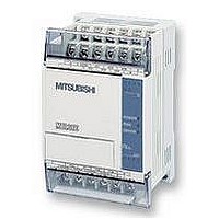
FX1S-30MR-ES/UL
Description
PLC, 16 IN, 14 RELAY OUT, 110V/2
Manufacturer
MITSUBISHI
Datasheet
1.FX1S-30MR-ESUL.pdf
(380 pages)
Specifications of FX1S-30MR-ES/UL
No. Of Analogue Inputs
16
No. Of Analogue Outputs
14
Ip/nema Rating
IP10
Approval Bodies
CE, CUL, UL
External Depth
49mm
External Length / Height
90mm
External Width
60mm
Mounting Type
Panel


FX Series Programmable Controllers
Chapter Contents
4. Devices in Detail....................................................................................4-1
4.1 Inputs ................................................................................................................... 4-1
4.2 Outputs ................................................................................................................ 4-2
4.3 Auxiliary Relays ................................................................................................... 4-3
4.4 State Relays ........................................................................................................ 4-6
4.5 Pointers ............................................................................................................. 4-10
4.6 Interrupt Pointers ............................................................................................... 4-11
4.7 Constant K ......................................................................................................... 4-14
4.8 Constant H......................................................................................................... 4-14
4.9 Timers................................................................................................................ 4-15
4.10 Counters ............................................................................................................ 4-19
4.11 High Speed Counters ........................................................................................ 4-22
4.12 Data Registers ................................................................................................... 4-30
4.13 Index Registers.................................................................................................. 4-35
4.14 Bits, Words, BCD and Hexadecimal .................................................................. 4-37
4.15 Floating Point And Scientific Notation ............................................................... 4-43
4.3.1 General Stable State Auxiliary Relays ...................................................................... 4-3
4.3.2 Battery Backed/ Latched Auxiliary Relays................................................................. 4-4
4.3.3 Special Diagnostic Auxiliary Relays .......................................................................... 4-5
4.3.4 Special Single Operation Pulse Relays ..................................................................... 4-5
4.4.1 General Stable State - State Relays ......................................................................... 4-6
4.4.2 Battery Backed/ Latched State Relays ...................................................................... 4-7
4.4.3 STL Step Relays ....................................................................................................... 4-8
4.4.4 Annunciator Flags ..................................................................................................... 4-9
4.6.1 Input Interrupts ........................................................................................................ 4-12
4.6.2 Timer Interrupts ....................................................................................................... 4-12
4.6.3 Disabling Individual Interrupts ................................................................................. 4-13
4.6.4 Counter Interrupts ................................................................................................... 4-13
4.9.1 General timer operation........................................................................................... 4-16
4.9.2 Selectable Timers.................................................................................................... 4-16
4.9.3 Retentive Timers ..................................................................................................... 4-17
4.9.4 Timers Used in Interrupt and ‘CALL’ Subroutines ................................................... 4-18
4.9.5 Timer Accuracy ....................................................................................................... 4-18
4.10.1 General/ Latched 16bit UP Counters ...................................................................... 4-20
4.10.2 General/ Latched 32bit Bi-directional Counters....................................................... 4-21
4.11.1 Basic High Speed Counter Operation ..................................................................... 4-23
4.11.2 Availability of High Speed Counters ....................................................................... 4-24
4.11.3 1 Phase Counters - User Start and Reset (C235 - C240) ....................................... 4-26
4.11.4 1 Phase Counters - Assigned Start and Reset (C246 to C250) .............................. 4-27
4.11.5 2 Phase Bi-directional Counters (C246 to C250) .................................................... 4-28
4.11.6 A/B Phase Counters (C252 to C255) ...................................................................... 4-29
4.12.1 General Use Registers ............................................................................................ 4-31
4.12.2 Battery Backed/ Latched Registers ......................................................................... 4-32
4.12.3 Special Diagnostic Registers................................................................................... 4-32
4.12.4 File Registers .......................................................................................................... 4-33
4.12.5 Externally Adjusted Registers ................................................................................. 4-34
4.13.1 Modifying a Constant............................................................................................... 4-36
4.13.2 Misuse of the Modifiers ........................................................................................... 4-36
4.13.3 Using Multiple Index Registers ................................................................................ 4-36
4.14.1 Bit Devices, Individual and Grouped ....................................................................... 4-37
4.14.2 Word Devices .......................................................................................................... 4-39
4.14.3 Interpreting Word Data ............................................................................................ 4-39
4.14.4 Two’s Compliment ................................................................................................... 4-42
4.15.1 Scientific Notation.................................................................................................... 4-44
4.15.2 Floating Point Format .............................................................................................. 4-45
4.15.3 Summary Of The Scientific Notation and Floating Point Numbers.......................... 4-46
Devices in Detail 4
Related parts for FX1S-30MR-ES/UL
Image
Part Number
Description
Manufacturer
Datasheet
Request
R

Part Number:
Description:
MITSUBISHI IGBT MODULES
Manufacturer:
MITSUBISHI
Datasheet:
Part Number:
Description:
MITSUBISHI INTELLIGENT POWER MODULES
Manufacturer:
MITSUBISHI
Datasheet:
Part Number:
Description:
TRANSFER-MOLD TYPE INSULATED TYPE
Manufacturer:
MITSUBISHI
Datasheet:
Part Number:
Description:
Manufacturer:
MITSUBISHI
Datasheet:
Part Number:
Description:
30A intelligent power module for flat-base type
Manufacturer:
MITSUBISHI
Datasheet:
Part Number:
Description:
15A - transistor module for medium power switching use, insulated type
Manufacturer:
MITSUBISHI
Datasheet:
Part Number:
Description:
5A power module for transfer-mold type insulated type
Manufacturer:
MITSUBISHI
Datasheet:
Part Number:
Description:
30A intelligent power module for flat-base type
Manufacturer:
MITSUBISHI
Datasheet:
Part Number:
Description:
TRANSFER-MOLD TYPE INSULATED TYPE
Manufacturer:
MITSUBISHI
Datasheet:
Part Number:
Description:
TRANSFER-MOLD TYPE INSULATED TYPE
Manufacturer:
MITSUBISHI
Datasheet:
Part Number:
Description:
20A - transistor module for medium power switching use, insulated type
Manufacturer:
MITSUBISHI
Datasheet:
Part Number:
Description:
20A - transistor module for medium power switching use, insulated type
Manufacturer:
MITSUBISHI
Datasheet: