HFBR-0573 Avago Technologies US Inc., HFBR-0573 Datasheet - Page 2
HFBR-0573
Manufacturer Part Number
HFBR-0573
Description
Fiber Optics, Evaluation Kit
Manufacturer
Avago Technologies US Inc.
Datasheet
1.HFBR-0573.pdf
(14 pages)
Specifications of HFBR-0573
Silicon Core Number
HFBR-5601/5602, HFCT-5611/5612
Features
One Fully Assembled GBIC Test Fixture And Literature
Tool / Board Applications
Transceivers
Main Purpose
Interface, Ethernet
Embedded
No
Utilized Ic / Part
HFBR-5601, HFBR-5602, HFCT-5611, HFCT-5612
Primary Attributes
GBIC Gigabit Ethernet or Fibre Channel Applications
Secondary Attributes
Hot Pluggable
Description/function
Fiber Optic Kit
Development Tool Type
Hardware / Software - Eval/Demo Board
Rohs Compliant
Yes
Lead Free Status / RoHS Status
Lead free / RoHS Compliant
For Use With/related Products
HFBR-560x, HFCT-561x
Lead Free Status / RoHS Status
Lead free / RoHS Compliant, Contains lead / RoHS non-compliant


The HFBR-5601 has been developed with 850 nm short
wavelength VCSEL technology while the HFCT-5611 is
based on 1300 nm long wavelength Fabry Perot laser
technology.
The HFBR-5601 complies with Annex G of the GBIC
specification Revision 5.4. In the 1000 BASE-SX
environment the HFBR-5601 achieves 220 m
transmission distance with 62.5 µm and 500 m with 50
µm multimode fiber respectively.
The HFCT-5611 complies with Annex F of the GBIC
specification Revision 5.4 and reaches 10 km with 9/
125 µm single mode fiber. Both the HFBR-5601 and
the HFCT-5611 are Class 1 Eye Safe laser devices.
Serial Identification
The HFBR-56xx and HFCT-5611 family complies with
Annex D (Module Definition 4) of the GBIC specification
Revision 5.4, which defines the Serial Identification
Protocol.
Definition 4 specifies a serial definition protocol. For
this definition, upon power up, MOD_DEF(1:2) (Pins 5
and 6 on the 20-pin connector) appear as NC. Pin 4 is
TTL ground. When the host system detects this
condition, it activates the public domain serial protocol.
The protocol uses the 2-wire serial CMOS E
protocol of the ATMEL AT24C01A or similar.
The data transfer protocol and the details of the
mandatory and vendor specific data structures are
defined in Annex D of the GBIC specification Revision
5.4.
Regulatory Compliance
See the Regulatory Compliance Table for the targeted
typical and measured performance for these
transceivers.
The overall equipment design will determine the level
it is able to be certified to. These transceiver
performance targets are offered as a figure of merit to
assist the designer in considering their use in
equipment designs.
Note: HFBR-5601 is non-compliant for Tx fault timing.
2
2
PROM
Electrostatic Discharge (ESD)
There are two design cases in which immunity to ESD
damage is important.
The first case is during handling of the transceiver prior
to inserting it into the host system. It is important to
use normal ESD handling precautions for ESD sensitive
devices. These precautions include using grounded
wrist straps, work benches, and floor mats in ESD
controlled areas.
The second case to consider is static discharges during
insertion of the GBIC into the host system. There are
two guide tabs integrated into the 20-pin connector
on the GBIC. These guide tabs are connected to circuit
ground. When the GBIC is inserted into the host system,
these tabs will engage before any of the connector pins.
The mating connector in the host system must have its
tabs connected to circuit ground. This discharges any
stray static charges and establishes a reference for the
power supplies that are sequenced later.
Electromagnetic Interference (EMI)
Most equipment designs utilizing these high-speed
transceivers from Avago Technologies will be required
to meet the requirements of FCC in the United States,
CENELEC EN55022 (CISPR 22) in Europe and VCCI in
Japan.
Immunity
Equipment utilizing these transceivers will be subject
to radio-frequency electromagnetic fields in some
environments. These transceivers have good immunity
to such fields due to their shielded design.
Eye Safety
Laser-based GBIC transceivers provide Class 1 (IEC
60825-1) and Class I (US 21 CFR[J]) laser eye safety by
design. Avago Technologies has tested the current
transceiver design for compliance with the
requirements listed below under normal operating
conditions and for compliance under single fault
conditions.
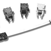
Outline Drawing
An outline drawing is shown in Figure 1. More detailed
drawings are shown in Gigabit Interface Converter
specification Rev. 5.4.
Related parts for HFBR-0573
Image
Part Number
Description
Manufacturer
Datasheet
Request
R

Part Number:
Description:
Fiber Optic Transmitters, Receivers, Transceivers 1300nm 155MBd 16-pin DIP ST Rx
Manufacturer:
Avago Technologies US Inc.

Part Number:
Description:
FIBER OPTIC TX 125 MBD 650N
Manufacturer:
Avago Technologies US Inc.
Datasheet:

Part Number:
Description:
Fiber Optic Evaluation Kit
Manufacturer:
Avago Technologies US Inc.
Datasheet:

Part Number:
Description:
RECEIVER FIBER OPTIC ST 266MBD
Manufacturer:
Avago Technologies US Inc.
Datasheet:

Part Number:
Description:
RCVR OPT HI SPEED VERS LINK HORZ
Manufacturer:
Avago Technologies US Inc.
Datasheet:

Part Number:
Description:
RCVR OPT HI SPEED VERS LINK VERT
Manufacturer:
Avago Technologies US Inc.
Datasheet:

Part Number:
Description:
TXRX OPTICAL 850NM VCSEL MT-RJ
Manufacturer:
Avago Technologies US Inc.
Datasheet:

Part Number:
Description:
TXRX MM SFP LC CONN BAIL DELATCH
Manufacturer:
Avago Technologies US Inc.
Datasheet:

Part Number:
Description:
TXRX MMF SFP GBE/FC BAIL DELATCH
Manufacturer:
Avago Technologies US Inc.
Datasheet:

Part Number:
Description:
XMITTER FIBER OPTIC 266MBD ST
Manufacturer:
Avago Technologies US Inc.
Datasheet:

Part Number:
Description:
OPTOCOUPLER GATE DRV 2A 16-SOIC
Manufacturer:
Avago Technologies US Inc.
Datasheet:
Part Number:
Description:
OPTOCOUPLER 2CH 2.5A 16-SOIC
Manufacturer:
Avago Technologies US Inc.
Datasheet:

Part Number:
Description:
OPTOCOUPLER GATE DRV 0.4A 16SOIC
Manufacturer:
Avago Technologies US Inc.
Datasheet:

Part Number:
Description:
OPTOCOUPLER 2.0A 250KHZ 8-DIP
Manufacturer:
Avago Technologies US Inc.
Datasheet:

Part Number:
Description:
OPTOCOUPLER 2.0A 250KHZ GW 8-SMD
Manufacturer:
Avago Technologies US Inc.
Datasheet: