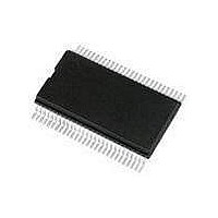
PCF8579TD NXP Semiconductors, PCF8579TD Datasheet - Page 24

PCF8579TD
Manufacturer Part Number
PCF8579TD
Description
LCD Drivers LCD DRVR DOT MATRIX
Manufacturer
NXP Semiconductors
Datasheet
1.PCF8579T1112.pdf
(41 pages)
Specifications of PCF8579TD
Maximum Clock Frequency
10 KHz
Operating Supply Voltage
2.5 V to 6 V
Maximum Power Dissipation
400 mW
Package / Case
VSO-56
Maximum Supply Current
20 uA
Lead Free Status / RoHS Status
Lead free / RoHS Compliant
Other names
PCF8579T/1,112
NXP Semiconductors
9. Limiting values
PCF8579_5
Product data sheet
The display status (all dots on or off and normal or inverse video) is set by the bits E[1:0]
of the set-mode command. For bank switching, the RAM bank corresponding to the top of
the display is set by the bits B[1:0] of the set-start-bank command. This is shown in
Figure
Table 13.
In accordance with the Absolute Maximum Rating System (IEC 60134).
[1]
Symbol
V
V
V
V
I
I
I
I
I
P
P
T
I
O
DD
DD(LCD)
SS
stg
DD
LCD
I
O
tot
o
According to the NXP store and transport conditions (document SNW-SQ-623 ) the devices have to be
stored at a temperature of +5 C to +45 C and a humidity of 25 % to 75 %.
18. This feature is useful when scrolling in alphanumeric applications.
Limiting values
Parameter
supply voltage
LCD supply voltage
input voltage
output voltage
input current
output current
supply current
LCD supply current
ground supply current
total power dissipation
output power
storage temperature
Rev. 05 — 11 May 2009
LCD column driver for dot matrix graphic displays
Conditions
V
V
V
V
per package
DD
LCD
DD
LCD
on pins SDA, SCL,
CLK, TEST, SA0
and OSC
V
SYNC and CLK
R0 to R7, R8/C8 to
R31/C31 and C32
to C39
3
related;
related;
and V
related;
related;
4
[1]
Min
V
V
V
-
-
0.5
0.5
0.5
10
10
50
50
50
65
DD
DD
DD
11
11
11
PCF8579
© NXP B.V. 2009. All rights reserved.
Max
+8.0
+8.0
+8.0
+8.0
+8.0
+8.0
+10
+10
+50
+50
+50
400
100
+150
24 of 41
Unit
V
V
V
V
V
V
mA
mA
mA
mA
mA
mW
mW
C


