ST7MDT1-DVP2/US STMicroelectronics, ST7MDT1-DVP2/US Datasheet
ST7MDT1-DVP2/US
Specifications of ST7MDT1-DVP2/US


Related parts for ST7MDT1-DVP2/US


ST7MDT1-DVP2/US Summary of contents
Page 1
... ST7MDT1-DVP2 Development Kit User Manual Ref: DOC-ST7MDT1-DVP2 Release 1.2 June 2001 ...
Page 2
... Please refer to relevant safety information. USE IN LIFE SUPPORT DEVICES OR SYSTEMS MUST BE EXPRESSLY AUTHORIZED. STMicroelectronics PRODUCTS ARE NOT AUTHORIZED FOR USE AS CRITICAL COMPONENTS IN LIFE SUPPORT DEVICES OR SYSTEMS WITHOUT THE EXPRESS WRITTEN APPROVAL OF STMicroelectronics. As used herein: 1. Life support devices or systems are those ...
Page 3
Chapter 1: Introduction . . . . . . . . . . . . . . . . . . . . . . . . . . . . . . . . . . . . . ...
Page 4
Pin descriptions .......................................................................................... 48 5.5 On-chip peripherals .................................................................................... 51 5.6 Hardware events ......................................................................................... 52 5.7 MDT1-DVP2 emulation features ................................................................. 55 Appendix A: EMC Conformity and Safety Requirements . . . . . . . . . . . . ...
Page 5
... In Situ Programming (ISP) ability (for MCUs that support this feature). This manual describes how to start and use the ST7MDT1-DVP2 Development Kit for the ST72254 series MCUs, allowing you to get acquainted with the ST7 microcontroller world and become familiar with the methods for developing and debugging ST7-driven applications ...
Page 6
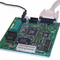
... MCU chip programming tool as summarized in the following sections. 1.1 Development board functional configurations Figure 1 shows the development board of the ST7MDT1-DVP2 Development Kit in an ST7 MCU Emulator configuration. ST7MDT1-DVP2 Development Kit in an ST7 MCU Programming Board configuration. Figure 1: Using the development board as an ST7 MCU emulator ...
Page 7
... ST7MDT1-DVP2 User Manual Figure 2: Using the development board as an ST7 MCU programming board Power Supply SDIP32 ZIF Socket for programming ST7MDT1-GP MCUs SO28 ZIF Socket (available as an option) for programming ST7MDT1-GP MCUs Figure 3: Using the development board for in situ programming (ISP) ...
Page 8
... Bold text highlights key terms, phrases and is used when referring to names of dialog boxes, windows and tabs within windows. Bold italic text denotes menu commands (or sequence of commands), options, buttons or check boxes which you must click in order to perform an action. 8/74 on page 11. on page 15. on page 39. ST7MDT1-DVP2 User Manual Chapter 4: Chapter 5: Hardware ...
Page 9
... ST7MDT1-DVP2 User Manual 1.4 Getting assistance For more information, application notes, FAQs and software updates on all the ST microcontroller families, check out the CD-ROM or our website: http://mcu.st.com For assistance on all ST microcontroller subjects you need help with using your emulator, use the contact list provided in ...
Page 10
... Introduction 10/74 ST7MDT1-DVP2 User Manual ...
Page 11
... ST7MDT1-DVP2 User Manual 2 GETTING STARTED 2.1 Your system requirements The ST7MDT1-DVP2 Development Kit (both hardware and software components) has been designed to work with PCs meeting the following requirements: • One of the following operating systems: Microsoft ® ® • Intel Pentium (or compatible) processor with minimum speed of 100 MHz. ...
Page 12
... LED) U1 LD1 JP1 U8 U9 U18 34-pin HE10 Application Connectors If you want to connect the emulator clock to OSCOUT, place a solder spot here (G1). ST7MDT1-DVP2 User Manual Parallel Port Connector P2 TP6 TP7 ISP DRV U5 U4 ST72254 Emulation Chip U10 Control RAM U14 U15 Emulation RAM ...
Page 13
... ST7MDT1-DVP2 User Manual 2.3 Installing the hardware To install the hardware, follow these steps: 1 Shut down and power-off the PC that connected to the development board. 2 Connect one end of the supplied parallel cable to the parallel connector (P2) on the development board. Connect the other end of the parallel cable to the LPT1 or LPT2 parallel port on your PC ...
Page 14
... Getting Started 14/74 ST7MDT1-DVP2 User Manual ...
Page 15
... ST7MDT1-DVP2 User Manual 3 STVD7 STVD7 is an integrated development environment that allows you to edit, debug and rebuild your application all from within STVD7. The following sections tell you: • Section 3.1 —how to install the STVD7 software, Section 3.2 • —how to launch STVD7, • ...
Page 16
... You may modify the toolchain path at any time from within STVD7—simply select Project>Toolchain Paths from the main menu to access the dialog box above. 16/74 Windows desktop, to enter the integrated ST7 ASM ST7MDT1-DVP2 User Manual , you must install STVD7 for DVP select Start>Programs>ST7 Tool ...
Page 17
... ST7MDT1-DVP2 User Manual 3.3 About STVD7 debugging features A number of advanced features are included in the STVD7 software: • Data Breakpoints on the occurrence of a memory access via a read operation or a write operation, or both. • Instruction Breakpoints on the occurrence of an opcode fetch. • A Trace window to view the contents of the trace buffer, which permanently ...
Page 18
... The visual environment is composed of two environments, one in the Build context and one in the Debug context (see • The debugging information includes information on breakpoints, memory mapping, advanced breakpoints programs, trace etc.. 18/74 Table 1 on page 20). on page 19). Section 3.11 on page 31). ST7MDT1-DVP2 User Manual ...
Page 19
... ST7MDT1-DVP2 User Manual 3.5 Toolchains and application files A quick summary of development toolchains and application file types supported by STVD7 will help you in setting up your workspace. Three different development toolchains are currently supported by the STVD7. Each type of toolchain has its own application and executable file types, project environment and building tools (i.e. linkers and convertors): • ...
Page 20
... Sample Make and/or Batch files (with default path .../spim11/spim11.bat .../c/cosmic/sample.bat .../c/hiware/build.mak .../c/hiware/rebuild.mak Forces a recom- C:/Program Files/Stm/st7toolchain/stvd7/ Table 2 on page 21 summarizes the way each ST7MDT1-DVP2 User Manual Description of 1 Make/Batch File ) Batch file that forces a recompile of the application. Batch file that forces a recompile of the application ...
Page 21
... ST7MDT1-DVP2 User Manual Table 2: Toolchain steps and their output files Toolchain: Compile or Assemble Step: Source File .asm Types Required asm -li macrost7.asm Options Resulting File .obj, .lst Types Linker Step: Required lyn macrost7.obj, macrost7 Options asm macrost7.asm Resulting File .map, .lst Types Converter obsend macrost7, f, macrost7 ...
Page 22
... STVD7 3.6 Creating a workspace 1 Select File>New Workspace . This command opens a new window where you define the name of your workspace and the directory in which you want to work. 22/74 ST7MDT1-DVP2 User Manual ...
Page 23
... ST7MDT1-DVP2 User Manual Then, click Next> . The New Workspace: Project Settings dialog box 2 appears: Here you enter your software toolchain, your executable filename and your build parameters either by typing or using the drop boxes. 3 Select the toolchain and enter the name of your application’s executable file. ...
Page 24
... There are a number of sample workspaces provided with STVD7 that you can open to get familiar with STVD7. These samples are listed in From the main menu, select File>Open Workspace. 1 This command opens a window where you can browse to any folder you wish, and select an existing workspace. 24/74 ST7MDT1-DVP2 User Manual Section 3.12 Table 1 on page 20. on ...
Page 25
... ST7MDT1-DVP2 User Manual 2 The Workspace window opens. When a workspace is opened, all of the predefined project settings are loaded into the STVD7. The Workspace window will show a structured representation of the project. mywork.wsp shows that it uses build.mak as the make file and sample.abs as the executable file ...
Page 26
... The range of debugging features available when you open a binary file only will be very restricted. You will only have access to basic debugging windows, such as the Disassembly and Memory Windows. 1 Launch STVD7 and select File>Open Workspace from the main menu. 26/74 ST7MDT1-DVP2 User Manual ...
Page 27
... ST7MDT1-DVP2 User Manual Browse to the folder where your binary file is stored, and select ST7 2 Application files (*.abs, *.s19, *.hex, *.elf) in the Files of type field. Select your binary file (*.abs, *.s19, *.hex or *.elf) and click Open . 3 The binary code in the executable file will be loaded into STVD7 and you will be able to access the Disassembly Window ...
Page 28
... You can change your settings here and continue running your application. When you exit STVD7, the system will ask you if you want to save these settings in the workspace you have been working in. If you choose yes , these will become your new workspace settings; if you choose no , these settings will be lost. 28/74 ST7MDT1-DVP2 User Manual ...
Page 29
... ST7MDT1-DVP2 User Manual The Toolchain Path... item invokes the following window: In this window, you can define your builder and/or Assembler paths. Clicking opens a browser window. 3.10 Saving workspaces Whenever the current workspace is closed automatically saved. This can happen either when exiting STVD or opening or creating a new workspace. ...
Page 30
... Toolbars and Commands). By default (i.e. when saved automatically) the workspace is saved as file < application >.wsp. The name of the file corresponds to the name used for the executable file (for example, < application >.abs for a Hiware executable file). 30/74 Figure 5: Options window ST7MDT1-DVP2 User Manual ...
Page 31
... ST7MDT1-DVP2 User Manual Note: Using the Configuration Setup dialog box (available from the MCU Configuration dialog box), you can also control what type of MCU configuration information is restored from a workspace file (*.wsp). 3.11 Debug context and Build context There are two STVD7 contexts, the build context and the debug context. Until now, in creating a workspace, and defining your project settings, you have been in the build context. To proceed step— ...
Page 32
... Note: The first time you enter into the Debug context after having created a new workspace, the MCU Configuration window will be opened automatically. 2 Select Tools>MCU Configuration from the main menu. The MCU Configuration window will open. 32/74 .) ST7MDT1-DVP2 User Manual . (STVD7 has ...
Page 33
... ST7MDT1-DVP2 User Manual An example of a typical MCU Configuration window is shown in MCU Name field Option configuration fields Note: The options shown in the above example may not be available for your particular target MCU. 3 Set the Target MCU. In the MCU name field, select the target device for which the application is intended from the dropdown box ...
Page 34
... The left column of the memory configuration window indicates the address range of each memory zone. The right column indicates the memory type of each zone. Depending on your target MCU, the available memory types may be: Peripherals, RAM, ROM, Stack, System, EEPROM, Reserved, Vectors, 34/74 ST7MDT1-DVP2 User Manual Graphic memory configuration viewer page 36 for ...
Page 35
... ST7MDT1-DVP2 User Manual Application. Some of these zones can have their type and size modified, others cannot be modified. Their definitions and properties are explained as follows: • Peripherals: Microcontroller internal or rebuilt peripherals registers. Their properties are defined as in the microcontroller datasheet. This memory cannot be modified. • ...
Page 36
... You can change a boundary address by dragging and dropping the triangle with the mouse to its new location. The triangle can be moved either up or down, left or right in the graphical viewer. 36/74 ST7MDT1-DVP2 User Manual ...
Page 37
... ST7MDT1-DVP2 User Manual The MCU configuration that you specify will, by default, be saved in a workspace file (*.wsp) for the project. The next time the application is opened, the STVD will automatically set the MCU configuration (as well as the layout of opened windows and other debug information) to the same conditions you had when you left the last debugging session ...
Page 38
... STVD7 38/74 ST7MDT1-DVP2 User Manual ...
Page 39
... ST7MDT1-DVP2 User Manual 4 PROGRAMMING ST7 DEVICES Once bug-free and ready for operation, your application program needs to be transferred into an ST7 MCU program space. With the ST7MDT1-DVP2 Development Kit, you may program the MCUs shown in Table 3 . Supported Device Device Group ST 72254 G1 Group 1 ...
Page 40
... Microcontrollers to program: SDIP32 SO28 PC parallel port connector 4.2 Programming methods 4.2.1 ZIF sockets The ST7MDT1-DVP2 development board is provided with a SDIP32 Zero Insertion Force (ZIF) socket which allows the programming of SDIP32 packaged MCUs. 40/74 DC/DC converters 3.3V ST7MDT1-DVP2 User Manual ST7MDT1-DVP2 Main Board ...
Page 41
... SO28 ZIF socket. The reference number for the SO28 ZIF socket (not supplied with the kit) is ENPLAS OTS28-1.27-04. 4.2.2 In situ programming In addition to classic MCU programming using ZIF sockets, the ST7MDT1-DVP2 Development Kit is provided with an In Situ Programming (ISP) functionality. This allows the user to program a target MCU mounted on an application board. Note: ...
Page 42
... To start the Windows Epromer (Winee), select Start>ST7 Tools>Windows Epromer . The Epromer main window appears: Click here to display the epromer configuration window 42/74 Note that as long as the programming board and the device to be programmed are not specified, the display area is blank. ST7MDT1-DVP2 User Manual ...
Page 43
... Configuring the Epromer Follow these steps the main window tool bar, click the configuration dialog box: 2 From the list, select the programming board for this ST7MDT1-DVP2 Development Kit: ST7MDT1-DVP2. 3 Select the parallel port (LPT1 or LPT2) on your PC to which the development board is connected. ...
Page 44
... To view in turn the memory mapping of a selection of devices plugged in, open the configuration window again, then the Select Chip list box, and click Apply. The display area of the main window changes while the list box stays open, for you to choose another chip if necessary. 44/74 ST7MDT1-DVP2 User Manual ...
Page 45
... ST7MDT1-DVP2 User Manual The name of the device to be programmed is displayed here The EPROM has been selected Progress bar (progress of the current task being executed by the Epromer) 7 Start your programming session. For more information on how to use the Windows Epromer, click the Help command in the main menu bar ...
Page 46
... Programming ST7 Devices 46/74 ST7MDT1-DVP2 User Manual ...
Page 47
... HARDWARE FEATURES 5.1 Link to PC The ST7MDT1-DVP2 development board communicates with your PC via the P2 connector connected to the PC parallel port (LPT1 or LPT2). Note: The parallel port of your PC should have been configured (in the BIOS settings) with either the Centronics, EPP, ECP or bidirectional parallel port configurations. ...
Page 48
... AC source. Specific sales types indicate the corresponding mains AC voltage supported: Sales Type ST7MDT1-DVP2/EU ST7MDT1-DVP2/UK ST7MDT1-DVP2/US Provided DC power specifications are as follows: Voltage Current complementary power supply inlet (ref.: JP1) is provided with the same specifications. When using this power supply, take care of the polarities marked nearby the two-point connector ...
Page 49
... ST7MDT1-DVP2 User Manual Table 4: SDIP32 passive probe pin assignments Probe Pin No The emulator clock is connected to OSCOUT only when a solder spot is placed the development board. 2) The emulator is only connected to VDD if a solder spot is placed the development board. The application voltage can be either 3 only. ...
Page 50
... Table 5: SO28 passive probe pin assignments Pin Name/Description RESET OSCIN (OSC1) 1 OSCOUT (OSC2) B7 Port B6 Port B5 Port B4 Port B3 Port B2 Port B1 Port B0 Port C5 Port C4 Port C3 Port ST7MDT1-DVP2 User Manual Probe Pin No. Pin Name/Description 15 C2 Port 16 C1 Port 17 C0 Port 18 A7 Port 19 A6 Port 20 A5 Port 21 A4 Port 22 ...
Page 51
... ST7MDT1-DVP2 User Manual 5.5 On-chip peripherals You can configure certain on-chip peripherals in STVD7’s MCU Configuration dialog box (refer to emulates your target device. The following options are available on all supported target devices: Clock You may choose the clock type (for example, on-board, external or on-chip microcontroller configuration option ...
Page 52
... There are three types of hardware event: • Event On (EVT_ON): The address where the event begins. • Event Off (EVT_OFF): The address where the event ends. • Event Hit (EVT_HIT): The event is active for the cycles in which one particular address is accessed. 52/74 ST7MDT1-DVP2 User Manual ...
Page 53
... ST7MDT1-DVP2 User Manual For information on how to insert hardware events, refer to the online help available with the STVD7. For more information on how to used hardware events to control the external output trigger (TRIGOUT) signal or the trace buffer filtering, refer to on page 53. 5.6.1 Trigger/trace settings ...
Page 54
... Hardware Features 5.6.2 External output trigger (TRIGOUT) The ST7MDT1-DVP2 development board features a special outlet (called TRIGOUT,) through which an external signal can be triggered out. The TRIGOUT pin is located on the board next to the passive probe flat connector (Ref.:TP24). From the Trigger/Trace Settings dialog box, you can choose the hardware event mode for the external signal ( EVT_OFF/EVT_ON or EVT_HIT ) ...
Page 55
... ST7MDT1-DVP2 User Manual 5.7 MDT1-DVP2 emulation features ST7MDT1-DVP2 Main Board DC/DC converter External Power Supply 3.3V Control Bus Status Bus FCT244 EXTCLK, TRIGIN Figure 8: Emulation architecture Data Bus On board clock 16 MHz PLD (2) Flex10K10a (3.3V) Ctrl / Status Bus PLD (1) Max7256a (3.3V) C ontrol Bus FCT244 ...
Page 56
... CPU itself. For devices in Group 2, you may only choose between on-board and external clock options. The External RC and xrd Resonator options are not available on the MDT1-DVP2 development board. ST7MDT1-DVP2 User Manual ST72251 G1/G2 ST72212 G2 ST72213 G1 ST72101 G1/G2 page 51 for instructions on how ...
Page 57
... ST7MDT1-DVP2 User Manual Emulation Function/Feature Temperature Tolerance Slow Mode Low Voltage Detection Supply Voltage Target Device Limitation or Discrepancy Group Independent of the target device used, the very large temperature tolerance scope of the ST72254 target device (- + not applicable to Groups 1 & 2 the development board. The development board has been designed to function at ambient temperature ...
Page 58
... SP register) will indicate the address 0x13F (and not 0x17F as would occur with the actual target device). Note that if a Stack Overflow break is not validated, any overflow of the stack will erase user variables (if any) situated between addresses 0x100 and 0x13F inclusive. ST7MDT1-DVP2 User Manual ...
Page 59
... ST7MDT1-DVP2 User Manual APPENDIX A: EMC CONFORMITY AND SAFETY REQUIREMENTS This development board respects the EMC requirements of the European guideline 89/336/EEC under the following conditions: • Any tester, equipment, or tool used at any production step or for any manipulation of semi-conductor devices have its shield connected to ground. ...
Page 60
... Appendix A: EMC Conformity and Safety Requirements 60/74 ST7MDT1-DVP2 User Manual ...
Page 61
... There is low capacitance on the MCU’s RESET pin. If you still cannot get ISP to work using your DVP, consult the application note AN1363/0401 entitled Workaround to ISP Mode Limitation on the ST7MDT1-DVP2 and ST7MDT2-DVP2 which can be found on ST’s website at: http://mcu.st.com This application note describes how to download and ...
Page 62
... Error (LPT1/LPT2): Interconnection failure. Verify your input/ output cable.” This may mean that the setup of the LPT1 or LPT2 port on your PC is not compatible with the ST7MDT1-DVP2 development board. To set up the port correctly: 1 Shut down and restart your PC in order to enter the BIOS setup. ...
Page 63
... ST7MDT1-DVP2 User Manual • clicking on the Hardware Test icon Caution: Be cautious in performing a Hardware Test on the emulator while an application is open. The opened application WILL BE corrupted by the hardware testing process. If you find that your application has been corrupted, simply close the application, and reopen it. ...
Page 64
... Appendix B: Troubleshooting The Hardware tests will be performed one by one, and the results summarized in the dialog box as shown at right: 64/74 ST7MDT1-DVP2 User Manual ...
Page 65
... ST7MDT1-DVP2 User Manual APPENDIX C:GLOSSARY Development Board The main component of the development kit, the development board consists primarily of a CPU which is capable of emulating the family of MCUs supported by the development kit, and a number of peripherals that allow you to perform debugging and programming functions. The development board contains a parallel port to communicate with your PC and so allow the running and debugging of applications designed for your target MCU ...
Page 66
... EPROM light source. Passive Probe A printed card having connector pins that allow you to connect the ST7MDT1- DVP2 to the MCU socket of the user application board. Using the passive probe allows the development board to emulate a target device embedded in your ...
Page 67
... ST7MDT1-DVP2 User Manual application. The passive probe is connected to the development board by two flat 34-pin cables. PC (Program Counter) The program counter is the CPU register that holds the address of the next instruction or operand that the CPU will use. RC network Resistor-capacitor network. SO Small outline. Designates a type of device package with two rows of pins for SMD or socket mounting ...
Page 68
... Appendix C: Glossary 68/74 ST7MDT1-DVP2 User Manual ...
Page 69
... ST7MDT1-DVP2 User Manual PRODUCT SUPPORT If you experience any problems with this product or if you need spare parts or repair, contact the distributor or ST sales office where you purchased the product. Getting prepared before you call Collect the following information about the product before contacting ST or your ...
Page 70
... You can get software updates from the ST Internet web site http://mcu.st.com. For information on firmware and hardware revisions, call your distributor or ST using the contact list given above. Hardware spare parts Yamaichi sockets You can order additional Yamaichi QFP sockets directly from Yamaichi at: http://www.yamaichi.de/Pu/quad_flat_pack/spec/a21-ic149.htm 70/74 ST7MDT1-DVP2 User Manual ...
Page 71
A Analog/Digital conversion limitations of .............................................. 58 C clock external ..................................................... 51 internal ...................................................... 51 normal mode ............................................. 51 option limitations ....................................... 56 slow mode................................................. 51 type ........................................................... 51 complementary power supply ........................... 48 D development board connecting to PC....................................... ...
Page 72
P parallel port troubleshooting connection problems ....... 62 parallel port of your PC ..................................... 47 passive probe definition of................................................ 66 general configuration .................................. 6 parts reference.......................................... 11 PC parallel port ................................................. 47 peripherals configuring target ...................................... 33 ports limitations of ...
Page 73
Z ZIF socket Index definition of ............................................... 67 ZIF sockets ....................................................... 40 73/74 ...
Page 74
... No license is granted by implication or otherwise under any patent or patent rights of STMicroelectronics. Specifications mentioned in this publication are subject to change without notice. This publication supersedes and replaces all information previously supplied. ...