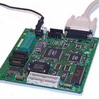
ST7MDT1-DVP2/US STMicroelectronics, ST7MDT1-DVP2/US Datasheet - Page 49

ST7MDT1-DVP2/US
Manufacturer Part Number
ST7MDT1-DVP2/US
Description
MCU, MPU & DSP Development Tools ST7 Development Kit
Manufacturer
STMicroelectronics
Datasheet
1.ST7MDT1-DVP2US.pdf
(74 pages)
Specifications of ST7MDT1-DVP2/US
Processor To Be Evaluated
ST72254
Interface Type
Parallel Port
Lead Free Status / RoHS Status
Lead free / RoHS Compliant
- Current page: 49 of 74
- Download datasheet (2Mb)
ST7MDT1-DVP2 User Manual
Probe Pin No.
1) The emulator clock is connected to OSCOUT only when a solder spot is
2) The emulator is only connected to VDD if a solder spot is placed in G2 on the
10
11
12
13
14
15
16
placed in G1 on the development board.
development board. The application voltage can be either 3.3 to 5 V only.
1
2
3
4
5
6
7
8
9
Table 4: SDIP32 passive probe pin assignments
Pin Name/Description
OSCOUT
OSCIN (OSC1)
Not used
Not used
RESET
B7 Port
B6 Port
B5 Port
B4 Port
B3 Port
B2 Port
B1 Port
B0 Port
C5 Port
C4 Port
C3 Port
1
(OSC2)
Probe Pin No.
17
18
19
20
21
22
23
24
25
26
27
28
29
30
31
32
Pin Name/Description
Not used (VPPTEST)
5 - Hardware Features
VSS (Ground)
Not used
Not used
C2 Port
C1 Port
C0 Port
A7 Port
A6 Port
A5 Port
A4 Port
A3 Port
A2 Port
A1 Port
A0 Port
VDD
2
49/74
Related parts for ST7MDT1-DVP2/US
Image
Part Number
Description
Manufacturer
Datasheet
Request
R

Part Number:
Description:
BOARD PROGRAMMING ST7
Manufacturer:
STMicroelectronics
Datasheet:

Part Number:
Description:
MCU, MPU & DSP Development Tools ST7 Evaluation Board
Manufacturer:
STMicroelectronics

Part Number:
Description:
MCU, MPU & DSP Development Tools ST7 Developmnt Board
Manufacturer:
STMicroelectronics

Part Number:
Description:
MCU, MPU & DSP Development Tools ST7 Emulator Board
Manufacturer:
STMicroelectronics

Part Number:
Description:
STMicroelectronics [RIPPLE-CARRY BINARY COUNTER/DIVIDERS]
Manufacturer:
STMicroelectronics
Datasheet:

Part Number:
Description:
STMicroelectronics [LIQUID-CRYSTAL DISPLAY DRIVERS]
Manufacturer:
STMicroelectronics
Datasheet:

Part Number:
Description:
BOARD EVAL FOR MEMS SENSORS
Manufacturer:
STMicroelectronics
Datasheet:

Part Number:
Description:
NPN TRANSISTOR POWER MODULE
Manufacturer:
STMicroelectronics
Datasheet:

Part Number:
Description:
TURBOSWITCH ULTRA-FAST HIGH VOLTAGE DIODE
Manufacturer:
STMicroelectronics
Datasheet:

Part Number:
Description:
Manufacturer:
STMicroelectronics
Datasheet:

Part Number:
Description:
DIODE / SCR MODULE
Manufacturer:
STMicroelectronics
Datasheet:

Part Number:
Description:
DIODE / SCR MODULE
Manufacturer:
STMicroelectronics
Datasheet:


