ST7MDT1-DVP2/US STMicroelectronics, ST7MDT1-DVP2/US Datasheet - Page 12
ST7MDT1-DVP2/US
Manufacturer Part Number
ST7MDT1-DVP2/US
Description
MCU, MPU & DSP Development Tools ST7 Development Kit
Manufacturer
STMicroelectronics
Datasheet
1.ST7MDT1-DVP2US.pdf
(74 pages)
Specifications of ST7MDT1-DVP2/US
Processor To Be Evaluated
ST72254
Interface Type
Parallel Port
Lead Free Status / RoHS Status
Lead free / RoHS Compliant


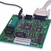
2 - Getting Started
12/74
SO28 ZIF
Device
Programming
Socket (not
provided with
Kit)
If you wish to
supply your
application
directly from the
development
board, via the
application
connector, place
a solder spot
here (G2 VCC
APP). Max.
100 mA.
SDIP32 ZIF
Device
Programming
Socket
Sticker with
serial and
version
numbers.
16 MHz Clock
ISP MCU
Driver
Push-button to
simulate behavior of
low voltage
detection (LVD) cell
of MCU during
voltage drop.
External Power
Supply
U12
U17
ISP SEL
U6
TP1
10-pin In Situ
Programming
(ISP) connector
Other Power
Inlet)
LVD RST
Figure 4: Development board layout
JP1
W2
If you want to connect the emulator
clock to OSCOUT, place a solder
spot here (G1).
LD1
2 x 34-pin HE10
Application Connectors
G2
Board Power ON
(green LED)
U18
U8
J2
J3
U1
G1
U9
U14
U4
External
Trigger
Output
U20
ISP DRV
External
Trigger
Input
U15
TP6
U21
U5
ST7MDT1-DVP2 User Manual
U10
P2
TP27
External
Clock
Input
TP7
Ground
TP28
Parallel Port Connector
U22
Trace
Probe
Inputs
[2,1,0]
Emulation
RAM
Control RAM
EPROM
User
Application
Program
Status LED
(lights up red
when running)
ST72254
Emulation
Chip
PLDs
Related parts for ST7MDT1-DVP2/US
Image
Part Number
Description
Manufacturer
Datasheet
Request
R

Part Number:
Description:
BOARD PROGRAMMING ST7
Manufacturer:
STMicroelectronics
Datasheet:
Part Number:
Description:
MCU, MPU & DSP Development Tools ST7 Evaluation Board
Manufacturer:
STMicroelectronics
Part Number:
Description:
MCU, MPU & DSP Development Tools ST7 Developmnt Board
Manufacturer:
STMicroelectronics

Part Number:
Description:
MCU, MPU & DSP Development Tools ST7 Emulator Board
Manufacturer:
STMicroelectronics
Part Number:
Description:
STMicroelectronics [RIPPLE-CARRY BINARY COUNTER/DIVIDERS]
Manufacturer:
STMicroelectronics
Datasheet:
Part Number:
Description:
STMicroelectronics [LIQUID-CRYSTAL DISPLAY DRIVERS]
Manufacturer:
STMicroelectronics
Datasheet:

Part Number:
Description:
BOARD EVAL FOR MEMS SENSORS
Manufacturer:
STMicroelectronics
Datasheet:
Part Number:
Description:
NPN TRANSISTOR POWER MODULE
Manufacturer:
STMicroelectronics
Datasheet:
Part Number:
Description:
TURBOSWITCH ULTRA-FAST HIGH VOLTAGE DIODE
Manufacturer:
STMicroelectronics
Datasheet:
Part Number:
Description:
Manufacturer:
STMicroelectronics
Datasheet:
Part Number:
Description:
DIODE / SCR MODULE
Manufacturer:
STMicroelectronics
Datasheet:
Part Number:
Description:
DIODE / SCR MODULE
Manufacturer:
STMicroelectronics
Datasheet: