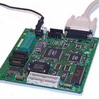
ST7MDT1-DVP2/US STMicroelectronics, ST7MDT1-DVP2/US Datasheet - Page 50

ST7MDT1-DVP2/US
Manufacturer Part Number
ST7MDT1-DVP2/US
Description
MCU, MPU & DSP Development Tools ST7 Development Kit
Manufacturer
STMicroelectronics
Datasheet
1.ST7MDT1-DVP2US.pdf
(74 pages)
Specifications of ST7MDT1-DVP2/US
Processor To Be Evaluated
ST72254
Interface Type
Parallel Port
Lead Free Status / RoHS Status
Lead free / RoHS Compliant
- Current page: 50 of 74
- Download datasheet (2Mb)
5 - Hardware Features
50/74
Probe Pin No.
1) The emulator clock is connected to OSCOUT only when a solder spot is
2) The emulator is only connected to VDD if a solder spot is placed in G2 on the
10
11
12
13
14
placed in G1 on the development board.
development board. The application voltage can be either 3.3 to 5 V only.
1
2
3
4
5
6
7
8
9
Table 5: SO28 passive probe pin assignments
Pin Name/Description
OSCOUT
OSCIN (OSC1)
RESET
B7 Port
B6 Port
B5 Port
B4 Port
B3 Port
B2 Port
B1 Port
B0 Port
C5 Port
C4 Port
C3 Port
1
(OSC2)
Probe Pin No.
15
16
17
18
19
20
21
22
23
24
25
26
27
28
ST7MDT1-DVP2 User Manual
Pin Name/Description
Not used (VPPTEST)
VSS (Ground)
C2 Port
C1 Port
C0 Port
A7 Port
A6 Port
A5 Port
A4 Port
A3 Port
A2 Port
A1 Port
A0 Port
VDD
2
Related parts for ST7MDT1-DVP2/US
Image
Part Number
Description
Manufacturer
Datasheet
Request
R

Part Number:
Description:
BOARD PROGRAMMING ST7
Manufacturer:
STMicroelectronics
Datasheet:

Part Number:
Description:
MCU, MPU & DSP Development Tools ST7 Evaluation Board
Manufacturer:
STMicroelectronics

Part Number:
Description:
MCU, MPU & DSP Development Tools ST7 Developmnt Board
Manufacturer:
STMicroelectronics

Part Number:
Description:
MCU, MPU & DSP Development Tools ST7 Emulator Board
Manufacturer:
STMicroelectronics

Part Number:
Description:
STMicroelectronics [RIPPLE-CARRY BINARY COUNTER/DIVIDERS]
Manufacturer:
STMicroelectronics
Datasheet:

Part Number:
Description:
STMicroelectronics [LIQUID-CRYSTAL DISPLAY DRIVERS]
Manufacturer:
STMicroelectronics
Datasheet:

Part Number:
Description:
BOARD EVAL FOR MEMS SENSORS
Manufacturer:
STMicroelectronics
Datasheet:

Part Number:
Description:
NPN TRANSISTOR POWER MODULE
Manufacturer:
STMicroelectronics
Datasheet:

Part Number:
Description:
TURBOSWITCH ULTRA-FAST HIGH VOLTAGE DIODE
Manufacturer:
STMicroelectronics
Datasheet:

Part Number:
Description:
Manufacturer:
STMicroelectronics
Datasheet:

Part Number:
Description:
DIODE / SCR MODULE
Manufacturer:
STMicroelectronics
Datasheet:

Part Number:
Description:
DIODE / SCR MODULE
Manufacturer:
STMicroelectronics
Datasheet:


