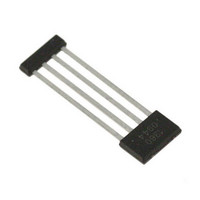
A1360LKTTN-T Allegro Microsystems Inc, A1360LKTTN-T Datasheet - Page 18

A1360LKTTN-T
Manufacturer Part Number
A1360LKTTN-T
Description
IC,HALL-EFFECT SENSOR,SINGLE-ENDED,BICMOS,SIP,4PIN,PLASTIC
Manufacturer
Allegro Microsystems Inc
Type
Linear - Unipolar, Bipolarr
Datasheet
1.A1360LKTTN-T.pdf
(25 pages)
Specifications of A1360LKTTN-T
Sensing Range
0.7mV/G ~ 1.4mV/G
Voltage - Supply
4.5 V ~ 5.5 V
Current - Supply
12mA
Current - Output (max)
10mA
Output Type
Analog, Ratiometric
Features
Programmable
Operating Temperature
-40°C ~ 150°C
Package / Case
4-SIP
Lead Free Status / RoHS Status
Lead free / RoHS Compliant
Other names
620-1233-2
A1360, A1361,
and A1362
Hold Mode
Hold mode allows multiple programmable parameters to be
tested simultaneously without permanently setting any values.
With the 136x programming logic, only two parameters located
in different zones can be addressed together. For example, only
the sensitivity and fine quiescent voltage offset parameters can be
temporarily set and tested simultaneously without permanently
setting their values. For unidirectional devices, the unidirectional
bit must be permanently blown before using the Hold Mode to
temporarily set and test the sensitivity and fine quiescent voltage
offset.
Powering the VCC supply automatically causes the device to
enter the first zone. Applying a high pulse, mid pulse, high pulse
sequence selects the Sensitivity register. The sensitivity can be set
to the desired value by applying the appropriate code pulses.
The next high-level pulse transitions the programming logic into
the second zone. Applying one mid level pulse causes the logic
to enter the Fine Quiescent Voltage Output register, and another
high-level pulse causes the logic to enter the Fine Quiescent
Voltage Output bit field. The fine quiescent voltage output can
be set to the desired level by applying the appropriate number of
mid-level pulses to the VOUT pin. (See figure 4.)
The addressed parameter values will be stored in the device logic
even after the programming drive voltage is removed from the
VOUT pin, allowing the output to be measured at any time dur-
ing the programming process.
After addressing and measuring the device output, cycle the sup-
ply to reset all of the register values. Registers can be addressed
and re-addressed an indefinite number of times. Once the final
Figure 4. Hold sequence for testing Sens and V
together.
Adjustable Bandwidth (50 kHz Maximum) and Analog Output
Low-Noise Programmable Linear Hall Effect Sensor ICs with
OUT(Q)
parameters
Programming Modes
desired code is found for each register, cycle the supply and blow
the bit field using Blow mode.
Note: For accurate time measurements, the blow capacitor,
C
Also note that both the Sensitivity and Fine Quiescent Voltage
Output registers should not be blown simultaneously. See the
Blow Mode section for additional information.
Try Mode
Try mode allows a single programmable parameter to be tested
without permanently setting its value. Try mode is a required step
of parameter blowing. (See the Blow Mode section for additional
information.) To select a parameter register in the first zone,
power the supply and enter the appropriate key-code pulse com-
bination (see figure 5). To select a parameter register in the sec-
ond zone, power the supply and apply two high voltage pulses,
followed by the appropriate key-code pulse combination (see
Figure 6). When addressing the bit field, each V
ments the value of the parameter register, up to the maximum
possible code (see the Programming Logic table). The addressed
parameter value is stored in the device even after the program-
ming drive voltage is removed from the VOUT pin, allowing its
value to be measured.
Note: For accurate time measurements, the blow capacitor,
C
To reset the bit field, and thus the value of the programmable
parameter, cycle the VCC supply voltage.
BLOW
BLOW
Figure 5. Pulses to enter Try mode, zone 1. Example shown is for
addressing the Sensitivity register. After addressing desired code,
cycle the supply to reset the bit field or apply a blow pulse to make the
parameter value permanent.
, should be removed during output voltage measurement.
, should be removed during output voltage measurement.
115 Northeast Cutoff
1.508.853.5000; www.allegromicro.com
Allegro MicroSystems, Inc.
Worcester, Massachusetts 01615-0036 U.S.A.
PM
pulse incre-
18


