A1360LKTTN-T Allegro Microsystems Inc, A1360LKTTN-T Datasheet - Page 20
A1360LKTTN-T
Manufacturer Part Number
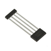
A1360LKTTN-T
Description
IC,HALL-EFFECT SENSOR,SINGLE-ENDED,BICMOS,SIP,4PIN,PLASTIC
Manufacturer
Allegro Microsystems Inc
Type
Linear - Unipolar, Bipolarr
Datasheet
1.A1360LKTTN-T.pdf
(25 pages)
Specifications of A1360LKTTN-T
Sensing Range
0.7mV/G ~ 1.4mV/G
Voltage - Supply
4.5 V ~ 5.5 V
Current - Supply
12mA
Current - Output (max)
10mA
Output Type
Analog, Ratiometric
Features
Programmable
Operating Temperature
-40°C ~ 150°C
Package / Case
4-SIP
Lead Free Status / RoHS Status
Lead free / RoHS Compliant
Other names
620-1233-2


A1360, A1361,
and A1362
Initial State
After system power-up, the programming logic is reset to a
known state. This is referred to as the Initial state. All the bit field
locations that have intact fuses are set to logic 0. While in the Ini-
tial state, any V
the zone 1 Parameter Selection state, apply a single V
VOUT pin. To enter the zone 2 Parameter Selection state, apply a
sequence of three V
Parameter Selection State
This state allows the selection of the parameter register contain-
ing the bit fields to be programmed. To select a parameter register
within the chosen zone, increment through the keys by sending
V
lowing programming parameters in zone 1:
and the following programming parameters in zone 2:
PM
1 pulse – Sens,
1 pulse – V
2 pulses – Coarse V
pulses on the VOUT pin. Register keys select among the fol-
User Power-down
Power-up
OUT(Q)
PM
Required
[Key sequence]
pulses on the VOUT pin are ignored. To enter
PH
OUT(Q)
pulses on the VOUT pin.
Parameter Selection
V
Bit Field Addressing
PM
and LOCK
V
V
V
(Zone 1)
PM
PH
PM
Initial
Sens
Adjustable Bandwidth (50 kHz Maximum) and Analog Output
Low-Noise Programmable Linear Hall Effect Sensor ICs with
1
V
V
PH
PH
V
PM
V
PM
V
Programming State Machine
PH
2
V
[Code sequence]
PH
V
Fuse Blowing
PH
V
PM
PH
pulse on
n= bits in
register
2
n
– 1
V
PH
V
PM
To enter the Bit Field Addressing state, send one V
VOUT pin.
Note: When parameter selection for zone 1 is bypassed (by send-
ing a second V
are ignored until after the V
Bit Field Addressing State
This state allows the selection of the individual bit fields to be
programmed in the selected parameter register (see the Program-
ming Logic table). To leave this state, either cycle device power
or blow the fuses for the selected code.
Note: Merely addressing the bit field does not permanently set
the value of the selected programming parameter; fuses must be
blown to do so.
Fuse Blowing State
To blow an addressed bit field, apply a V
pin. Power to the device should then be cycled before additional
programming is attempted.
Note: Each bit representing a decimal code must be blown indi-
vidually (see the Fuse Blowing section).
Parameter Selection
(Zone 2)
V
V
PH
PH
V
V
V
PH
Bit Field Addressing
PM
PM
PH
V
OUT(Q)
(Fine)
pulse) no register is selected, and V
1
= V
= V
V
V
V
PH
PM
PH
V
V
P(LOW)
P(LOW)
PM
PM
[Key sequence]
115 Northeast Cutoff
1.508.853.5000; www.allegromicro.com
Allegro MicroSystems, Inc.
Worcester, Massachusetts 01615-0036 U.S.A.
PH
V
Coarse
[Code sequence]
or Lock
OUT(Q)
2
pulse is sent to enter zone 2.
→ V
→ V
V
V
PH
PH
V
V
P(HIGH)
P(MID)
PM
PM
PH
→ V
n= bits in
2
register
→ V
pulse on the VOUT
n
– 1
V
P(LOW)
PH
P(LOW)
V
PH
PM
PM
pulse on the
pulses
20
Related parts for A1360LKTTN-T
Image
Part Number
Description
Manufacturer
Datasheet
Request
R

Part Number:
Description:
Manufacturer:
Allegro Micro Systems, Inc.
Datasheet:

Part Number:
Description:
CONN RECEPT CPC 4POS REV SER 1
Manufacturer:
Tyco Electronics
Datasheet:

Part Number:
Description:
IC, HALL EFFECT SENSOR, Linear, SOIC-8
Manufacturer:
Allegro Microsystems Inc
Datasheet:
Part Number:
Description:
IC, HALL EFFECT SENSOR, Linear, SOIC-8
Manufacturer:
Allegro Microsystems Inc
Datasheet:
Part Number:
Description:
IC, HALL EFFECT SENSOR, Linear, SOIC-8
Manufacturer:
Allegro Microsystems Inc
Datasheet:

Part Number:
Description:
IC SWITCH INTERFACE 2CHAN 8-SOIC
Manufacturer:
Allegro Microsystems Inc
Datasheet:

Part Number:
Description:
IC SMOKE DETECTOR ION 16-DIP
Manufacturer:
Allegro Microsystems Inc
Datasheet:
Part Number:
Description:
IC SMOKE DETECTOR ION 16-DIP
Manufacturer:
Allegro Microsystems Inc
Datasheet:
Part Number:
Description:
IC SMOKE DETECTOR ION 16-DIP
Manufacturer:
Allegro Microsystems Inc
Datasheet:
Part Number:
Description:
IC SMOKE DETECTOR PHOTO 16-DIP
Manufacturer:
Allegro Microsystems Inc
Datasheet:
Part Number:
Description:
IC SMOKE DETECTOR ION 16-DIP
Manufacturer:
Allegro Microsystems Inc
Datasheet:
Part Number:
Description:
IC SMOKE DETECTOR PHOTO 16-DIP
Manufacturer:
Allegro Microsystems Inc
Datasheet:
Part Number:
Description:
IC SMOKE DETECTOR PHOTO 16-DIP
Manufacturer:
Allegro Microsystems Inc
Datasheet:
Part Number:
Description:
IC SMOKE DETECTOR ION 16-DIP
Manufacturer:
Allegro Microsystems Inc
Datasheet:
Part Number:
Description:
IC SMOKE DETECTOR PHOTO 16-SOIC
Manufacturer:
Allegro Microsystems Inc
Datasheet: