A1360LKTTN-T Allegro Microsystems Inc, A1360LKTTN-T Datasheet - Page 9
A1360LKTTN-T
Manufacturer Part Number
A1360LKTTN-T
Description
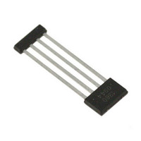
IC,HALL-EFFECT SENSOR,SINGLE-ENDED,BICMOS,SIP,4PIN,PLASTIC
Manufacturer
Allegro Microsystems Inc
Type
Linear - Unipolar, Bipolarr
Datasheet
1.A1360LKTTN-T.pdf
(25 pages)
Specifications of A1360LKTTN-T
Sensing Range
0.7mV/G ~ 1.4mV/G
Voltage - Supply
4.5 V ~ 5.5 V
Current - Supply
12mA
Current - Output (max)
10mA
Output Type
Analog, Ratiometric
Features
Programmable
Operating Temperature
-40°C ~ 150°C
Package / Case
4-SIP
Lead Free Status / RoHS Status
Lead free / RoHS Compliant
Other names
620-1233-2


A1360, A1361,
and A1362
Power-On Time
age, the device requires a finite time to power its internal com-
ponents before responding to an input magnetic field. Power-On
Time, t
to settle within ±10% of its steady state value under an applied
magnetic field, after the power supply has reached its minimum
specified operating voltage, V
chart.
Propagation Delay Time (t
output to reflect a change in the applied magnetic field. Propaga-
tion delay can be considered as a fixed time offset and may be
compensated.
V
90% V
V
CC
CC
PO
(min.)
(typ.)
(%)
, is defined as: the time it takes for the output voltage
OUT
90
0
V
0
When the supply is ramped to its operating volt-
t
1
Propagation Delay Time, t
t
t
1
2
V
= time at which power supply reaches
= time at which output voltage settles
CC
minimum specified operating voltage
within ±10% of its steady state value
under an applied magnetic field
pd
Applied Magnetic Field
t
2
CC
)
Transducer Output
The time required for the device
(min), as shown in the following
t
PO
Adjustable Bandwidth (50 kHz Maximum) and Analog Output
V
Low-Noise Programmable Linear Hall Effect Sensor ICs with
OUT
pd
Characteristic Definitions
t
+t
Rise Time (t
reaches 10% of its full scale value, and b) when it reaches 90%
of its full scale value. The rise time to a step response is used to
derive the bandwidth of the linear device, in which ƒ(–3 dB) =
0.35 / t
current losses observed in the conductive IC ground plane.
Response Time (t
the applied magnetic field reaches 90% of its final value, and b)
when the device reaches 90% of its output corresponding to the
applied magnetic field.
r
. Both t
(%)
(%)
90
10
90
0
0
r
)
The time interval between a) when the device
r
and t
RESPONSE
RESPONSE
115 Northeast Cutoff
1.508.853.5000; www.allegromicro.com
Applied Magnetic Field
Applied Magnetic Field
Allegro MicroSystems, Inc.
Worcester, Massachusetts 01615-0036 U.S.A.
)
Rise Time, t
Response Time, t
The time interval between a) when
Transducer Output
Transducer Output
are detrimentally affected by eddy
r
RESPONSE
t
t
9
Related parts for A1360LKTTN-T
Image
Part Number
Description
Manufacturer
Datasheet
Request
R

Part Number:
Description:
Manufacturer:
Allegro Micro Systems, Inc.
Datasheet:

Part Number:
Description:
CONN RECEPT CPC 4POS REV SER 1
Manufacturer:
Tyco Electronics
Datasheet:

Part Number:
Description:
IC, HALL EFFECT SENSOR, Linear, SOIC-8
Manufacturer:
Allegro Microsystems Inc
Datasheet:
Part Number:
Description:
IC, HALL EFFECT SENSOR, Linear, SOIC-8
Manufacturer:
Allegro Microsystems Inc
Datasheet:
Part Number:
Description:
IC, HALL EFFECT SENSOR, Linear, SOIC-8
Manufacturer:
Allegro Microsystems Inc
Datasheet:

Part Number:
Description:
IC SWITCH INTERFACE 2CHAN 8-SOIC
Manufacturer:
Allegro Microsystems Inc
Datasheet:

Part Number:
Description:
IC SMOKE DETECTOR ION 16-DIP
Manufacturer:
Allegro Microsystems Inc
Datasheet:
Part Number:
Description:
IC SMOKE DETECTOR ION 16-DIP
Manufacturer:
Allegro Microsystems Inc
Datasheet:
Part Number:
Description:
IC SMOKE DETECTOR ION 16-DIP
Manufacturer:
Allegro Microsystems Inc
Datasheet:
Part Number:
Description:
IC SMOKE DETECTOR PHOTO 16-DIP
Manufacturer:
Allegro Microsystems Inc
Datasheet:
Part Number:
Description:
IC SMOKE DETECTOR ION 16-DIP
Manufacturer:
Allegro Microsystems Inc
Datasheet:
Part Number:
Description:
IC SMOKE DETECTOR PHOTO 16-DIP
Manufacturer:
Allegro Microsystems Inc
Datasheet:
Part Number:
Description:
IC SMOKE DETECTOR PHOTO 16-DIP
Manufacturer:
Allegro Microsystems Inc
Datasheet:
Part Number:
Description:
IC SMOKE DETECTOR ION 16-DIP
Manufacturer:
Allegro Microsystems Inc
Datasheet:
Part Number:
Description:
IC SMOKE DETECTOR PHOTO 16-SOIC
Manufacturer:
Allegro Microsystems Inc
Datasheet: