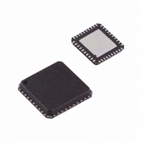
AD8195ACPZ-R7 Analog Devices Inc, AD8195ACPZ-R7 Datasheet - Page 14

AD8195ACPZ-R7
Manufacturer Part Number
AD8195ACPZ-R7
Description
Front Panel HDMI Buffer
Manufacturer
Analog Devices Inc
Datasheet
1.AD8195ACPZ-R7.pdf
(20 pages)
Specifications of AD8195ACPZ-R7
Function
Switch
Circuit
1 x 1:1
Voltage Supply Source
Single Supply
Voltage - Supply, Single/dual (±)
3 V ~ 3.6 V
Current - Supply
40mA
Operating Temperature
-40°C ~ 85°C
Mounting Type
Surface Mount
Package / Case
40-VFQFN, CSP Exposed Pad
Lead Free Status / RoHS Status
Lead free / RoHS Compliant
Available stocks
Company
Part Number
Manufacturer
Quantity
Price
Company:
Part Number:
AD8195ACPZ-R7
Manufacturer:
MITSUBISHI
Quantity:
101
AD8195
APPLICATIONS INFORMATION
FRONT PANEL BUFFER FOR ADVANCED TV
A front panel input provides easy access to an HDMI connector
for connecting devices, such as an HD camcorder or video game
console, to an HDTV. In designs where the main PCB is not
near the side or front of the HDTV, a front panel HDMI input
must be connected to the main board through a cable. The
AD8195 enables the implementation of a front or side panel
HDMI input for an HDTV by buffering the HDMI signals and
compensating for the cable interconnect to the main board.
A simplified typical front panel buffer circuit is shown in Figure 29.
The AD8195 is designed to have an HDMI/DVI receiver pinout
at its input and a transmitter pinout at its output. This makes
the AD8195 ideal for use in television set front panel connectors
and AVR-type applications where a designer routes both the
inputs and the outputs directly to HDMI/DVI connectors.
One advantage of the AD8195 in a television set front panel
connector is that all of the high speed signals can be routed on
one side (the topside) of the board. The AD8195 provides 12 dB
of input equalization so it can compensate for the signal degra-
dation of long input cables. In addition, the AD8195 can also
provide up to 6 dB of output preemphasis that boosts the output
TMDS signals and allows the AD8195 to precompensate when
driving long PCB traces or high loss output cables. The net
effect of the input equalization and output preemphasis of the
AD8195 is that the AD8195 can compensate for the signal
degradation of both the input and output cables; it acts to
reopen a closed input data eye and transmit a full swing HDMI
signal to an end receiver.
Placement of a shunt resistor from the negative terminal of the
input TMDS clock differential pair to ground is recommended
to prevent amplification of ambient noise resulting in a large
swing signal at the input of the HDMI receiver.
For the CEC and DDC buffer circuits to be active when the
local supply is off, power must be provided to the AD8195
AMUXVCC supply pin from the HDMI source. The 5 V from
the HDMI connector and the local 5 V supply should be
isolated with diodes to prevent contention. Additionally, the
diodes should be selected such that the forward voltage drop
from the local supply is less than from the HDMI source so that
Rev. 0 | Page 14 of 20
current is not drawn from the HDMI source when the local
supply is on.
The rise time of the CEC buffer output is set by the time
constant of the pull-up resistance and the capacitance on the
output node. An additional external pull-up resistance is
recommended at the CEC output to allow for optimal rise
times. A Thevenin equivalent 2 kΩ pull-up to 3.3 V is shown in
Figure 30.
The VREF_IN and VREF_OUT pins are voltage references for
the input and output pins of DDC buffer. The external pull-up
resistors for the DDC bus should be connected to the same
voltage as applied to the respective VREF pin.
Typically, an EDID EEPROM is placed prior to the AD8195, as
shown in Figure 30. If desired, the EDID EEPROM can be
downstream of the AD8195. This optional configuration is also
illustrated in Figure 30. Regardless of the configuration, the
pull-up voltage at the DDC output should be on even when the
local system power supply is off.
To ensure that the AD8195 operates properly, Pin 21 (COMP)
should be tied to ground through a 10 μF bypass capacitor. A
34 kΩ pull-up resistor from COMP to AMUXVCC is integrated
on chip.
AD8195
Figure 29. AD8195 as a Front Panel Buffer for an HDTV
CABLE
HDTV SET
MAIN PCB
HDMI RX


