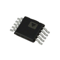
ADP1873ARMZ-0.3-R7 Analog Devices Inc, ADP1873ARMZ-0.3-R7 Datasheet - Page 23

ADP1873ARMZ-0.3-R7
Manufacturer Part Number
ADP1873ARMZ-0.3-R7
Description
300kHz, Light Load Eff Enabled
Manufacturer
Analog Devices Inc
Datasheet
1.ADP1872ARMZ-0.6-R7.pdf
(40 pages)
Specifications of ADP1873ARMZ-0.3-R7
Pwm Type
Current Mode
Number Of Outputs
1
Frequency - Max
300kHz
Duty Cycle
84%
Voltage - Supply
2.75 V ~ 20 V
Buck
Yes
Boost
No
Flyback
No
Inverting
No
Doubler
No
Divider
No
Cuk
No
Isolated
No
Operating Temperature
-40°C ~ 125°C
Package / Case
10-MSOP, Micro10™, 10-uMAX, 10-uSOP
Frequency-max
300kHz
Lead Free Status / RoHS Status
Lead free / RoHS Compliant
Other names
ADP1873ARMZ-0.3-R7TR
Available stocks
Company
Part Number
Manufacturer
Quantity
Price
Company:
Part Number:
ADP1873ARMZ-0.3-R7
Manufacturer:
Analog Devices Inc
Quantity:
1 900
APPLICATIONS INFORMATION
FEEDBACK RESISTOR DIVIDER
The required resistor divider network can be determine for a
given V
is fixed at 0.6 V. Selecting values for R
minimum output load current of the converter. Therefore, for a
given value of R
INDUCTOR SELECTION
The inductor value is inversely proportional to the inductor
ripple current. The peak-to-peak ripple current is given by
where K
The equation for the inductor value is given by
where:
VIN is the high voltage input.
V
f
and 1.0 MHz).
When selecting the inductor, choose an inductor saturation rating
that is above the peak current level and then calculate the
inductor current ripple (see the Valley Current-Limit Setting
section and Figure 78).
SW
OUT
is the controller switching frequency (300 kHz, 600 kHz,
R
Δ
L
is the desired output voltage.
T
I
52
50
48
46
44
42
40
38
36
34
32
30
28
26
24
22
20
18
16
14
12
10
=
OUT
L
8
I
=
6
Figure 78. Peak Current vs. Valley Current Threshold for
is typically 0.33.
(
=
VIN
R
Δ
value because the internal band gap reference (V
K
B
I
33%, 40%, and 50% of Inductor Ripple Current
8
I
L
×
−
×
×
(
B
V
10
V
, the R
I
f
LOAD
OUT
OUT
SW
0
12
6 .
)
−
VALLEY CURRENT LIMIT (A)
T
≈
×
V
0
14
value can be determined by
V
6 .
I
VIN
LOAD
OUT
V)
3
16
18
20
T
and R
ΔI = 40%
22
ΔI = 50%
24
B
determines the
ΔI = 33%
26
28
30
REF
Rev. A | Page 23 of 40
)
Table 7. Recommended Inductors
L
(μH)
0.12
0.22
0.47
0.72
0.9
1.2
1.0
1.4
2.0
0.8
OUTPUT RIPPLE VOLTAGE (ΔV
The output ripple voltage is the ac component of the dc output
voltage during steady state. For a ripple error of 1.0%, the output
capacitor value needed to achieve this tolerance can be determined
using the following equation. (Note that an accuracy of 1.0% is
only possible during steady state conditions, not during load
transients.)
OUTPUT CAPACITOR SELECTION
The primary objective of the output capacitor is to facilitate
the reduction of the output voltage ripple; however, the output
capacitor also assists in the output voltage recovery during load
transient events. For a given load current step, the output voltage
ripple generated during this step event is inversely proportional
to the value chosen for the output capacitor. The speed at which
the output voltage settles during this recovery period depends
on where the crossover frequency (loop bandwidth) is set. This
crossover frequency is determined by the output capacitor, the
equivalent series resistance (ESR) of the capacitor, and the
compensation network.
To calculate the small signal voltage ripple (output ripple
voltage) at the steady state operating point, use the following
equation:
where ESR is the equivalent series resistance of the output
capacitors.
To calculate the output load step, use the following equation:
where ΔV
a given positive load current step (ΔI
ΔV
C
C
OUT
OUT
DCR
(mΩ)
0.33
0.33
0.8
1.65
1.6
1.8
3.3
3.2
2.6
RR
DROOP
= (0.01) × V
=
=
2
Δ
×
I
I
(A)
55
30
50
35
28
25
20
24
22
27.5
SAT
L
is the amount that V
×
f
SW
⎛
⎜
⎜
⎝
8
×
Dimensions
(mm)
10.2 × 7
10.2 × 7
14.2 × 12.8
10.5 × 10.2
13 × 12.8
10.5 × 10.2
10.5 × 10.2
14 × 12.8
13.2 × 12.8
×
(
OUT
Δ
f
SW
V
DROOP
×
[
Δ
Δ
V
I
LOAD
−
RIPPLE
ADP1872/ADP1873
(
Manufacturer
Würth Elektronic
Würth Elektronic
Würth Elektronic
Würth Elektronic
Würth Elektronic
Würth Elektronic
Würth Elektronic
Würth Elektronic
Würth Elektronic
Sumida
Δ
1
OUT
I
LOAD
LOAD
−
RR
is allowed to deviate for
(
)
).
Δ
×
I
L
ESR
×
ESR
))
)
]
Model No.
744303012
744303022
744355147
744325072
744355090
744325120
7443552100
744318180
7443551200
CEP125U-0R8
⎞
⎟
⎟
⎠


