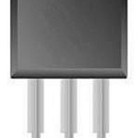
BT149G AMO NXP Semiconductors, BT149G AMO Datasheet

BT149G AMO
Specifications of BT149G AMO
Related parts for BT149G AMO
BT149G AMO Summary of contents
Page 1
BT149 series Thyristors logic level Rev. 04 — 20 August 2004 1. Product profile 1.1 General description Passivated, sensitive gate thyristors in a SOT54 plastic package. 1.2 Features Designed to be interfaced directly to microcontrollers, logic integrated circuits and other ...
Page 2
Philips Semiconductors 3. Ordering information Table 2: Ordering information Type number Package Name Description BT149B - plastic single-ended leaded (through hole) package; 3 leads BT149D BT149G 4. Limiting values Table 3: Limiting values In accordance with the Absolute Maximum Rating ...
Page 3
Philips Semiconductors 0.8 P tot (W) 0.6 0 form factor = I /I T(RMS) T(AV) Fig 1. Total power dissipation as a function of average on-state current; maximum values TSM (A) 8 ...
Page 4
Philips Semiconductors TSM ( ms. p Fig 3. Non-repetitive peak on-state current as a function of pulse width for sinusoidal currents; maximum values T(RMS) (A) 1.5 1 ...
Page 5
Philips Semiconductors 5. Thermal characteristics Table 4: Thermal characteristics Symbol Parameter R thermal resistance from junction to th(j-lead) lead R thermal resistance from junction to th(j-a) ambient th(j-lead) (K/ ...
Page 6
Philips Semiconductors 6. Characteristics Table 5: Characteristics unless otherwise stated. j Symbol Parameter Static characteristics I gate trigger current GT I latching current L I holding current H V on-state voltage T V gate trigger voltage ...
Page 7
Philips Semiconductors 1.6 V GT(Tj) V GT(25 C) 1.2 0.8 0 Fig 7. Normalized gate trigger voltage as a function of junction temperature ( (1) (2) (3) 0 0.4 1.2 ...
Page 8
Philips Semiconductors 3 I H(Tj Fig 11. Normalized holding current as a function of junction temperature. 7. Package information Epoxy meets requirements of UL94 V-0 ...
Page 9
Philips Semiconductors 8. Package outline Plastic single-ended leaded (through hole) package; 3 leads DIMENSIONS (mm are the original dimensions) UNIT 5.2 0.48 0.66 0.45 mm 5.0 0.40 ...
Page 10
Philips Semiconductors 9. Revision history Table 6: Revision history Document ID Release date BT149_SERIES_4 20040820 • Modifications: The format of this data sheet has been redesigned to comply with the new presentation and information standard of Philips Semiconductors. BT149_SERIES_3 20010902 ...
Page 11
Philips Semiconductors 10. Data sheet status [1] Level Data sheet status Product status I Objective data Development II Preliminary data Qualification III Product data Production [1] Please consult the most recently issued data sheet before initiating or completing a design. ...
Page 12
Philips Semiconductors 14. Contents 1 Product profi 1.1 General description ...


