SI7900AEDN-T1-E3 Vishay, SI7900AEDN-T1-E3 Datasheet - Page 9
SI7900AEDN-T1-E3
Manufacturer Part Number
SI7900AEDN-T1-E3
Description
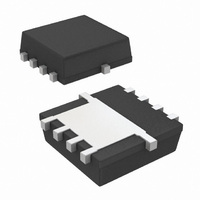
MOSFET DUAL N-CH 20V 1212-8
Manufacturer
Vishay
Series
TrenchFET®r
Specifications of SI7900AEDN-T1-E3
Fet Type
2 N-Channel (Dual)
Fet Feature
Logic Level Gate
Rds On (max) @ Id, Vgs
26 mOhm @ 8.5A, 4.5V
Drain To Source Voltage (vdss)
20V
Current - Continuous Drain (id) @ 25° C
6A
Vgs(th) (max) @ Id
900mV @ 250µA
Gate Charge (qg) @ Vgs
16nC @ 4.5V
Power - Max
1.5W
Mounting Type
Surface Mount
Package / Case
PowerPAK® 1212-8 Dual
Transistor Polarity
N Channel
Continuous Drain Current Id
8.5A
Drain Source Voltage Vds
20V
On Resistance Rds(on)
36mohm
Rds(on) Test Voltage Vgs
12V
Threshold Voltage Vgs Typ
900mV
Lead Free Status / RoHS Status
Lead free / RoHS Compliant
Other names
SI7900AEDN-T1-E3TR
Available stocks
Company
Part Number
Manufacturer
Quantity
Price
Company:

Part Number:
SI7900AEDN-T1-E3
Manufacturer:
VISHAY
Quantity:
4 189
Part Number:
SI7900AEDN-T1-E3
Manufacturer:
VISHAY/威世
Quantity:
20 000


THERMAL PERFORMANCE
Introduction
A basic measure of a device’s thermal performance is
the junction-to-case thermal resistance, Rθjc, or the
junction to- foot thermal resistance, Rθjf. This parameter
is measured for the device mounted to an infinite heat
sink and is therefore a characterization of the device
only, in other words, independent of the properties of the
object to which the device is mounted. Table 1 shows a
comparison of the PowerPAK 1212-8, PowerPAK SO-8,
standard TSSOP-8 and SO-8 equivalent steady state
performance.
By minimizing the junction-to-foot thermal resistance, the
MOSFET die temperature is very close to the tempera-
ture of the PC board. Consider four devices mounted on
a PC board with a board temperature of 45 °C (Figure 4).
Suppose each device is dissipating 2 W. Using the junc-
tion-to-foot thermal resistance characteristics of the
PowerPAK 1212-8 and the other SMT packages, die
temperatures are determined to be 49.8 °C for the Pow-
erPAK 1212-8, 85 °C for the standard SO-8, 149 °C for
standard TSSOP-8, and 125 °C for TSOP-6. This is a
4.8 °C rise above the board temperature for the Power-
PAK 1212-8, and over 40 °C for other SMT packages. A
4.8 °C rise has minimal effect on r
of over 40 °C will cause an increase in r
as 20 %.
Document Number 71681
03-Mar-06
TABLE 1: EQIVALENT STEADY STATE PERFORMANCE
Thermal Resiatance R
PowerPAK 1212
Configuration
Package
2.4 °C/W
PC Board at 45 °C
thJC
49.8 °C
(C/W)
Single
DS(ON)
Standard SO-8
20
Figure 4. Temperature of Devices on a PC Board
SO-8
whereas a rise
DS(ON)
Dual
40
20 °C/W
as high
85 °C
Single
52
TSSOP-8
Spreading Copper
Designers add additional copper, spreading copper, to
the drain pad to aid in conducting heat from a device. It
is helpful to have some information about the thermal
performance for a given area of spreading copper.
Figure 5 and Figure 6 show the thermal resistance of a
PowerPAK 1212-8 single and dual devices mounted on
a 2-in. x 2-in., four-layer FR-4 PC boards. The two inter-
nal layers and the backside layer are solid copper. The
internal layers were chosen as solid copper to model the
large power and ground planes common in many appli-
cations. The top layer was cut back to a smaller area and
at each step junction-to-ambient thermal resistance
measurements were taken. The results indicate that an
area above 0.2 to 0.3 square inches of spreading copper
gives no additional thermal performance improvement.
A subsequent experiment was run where the copper on
the back-side was reduced, first to 50 % in stripes to
mimic circuit traces, and then totally removed. No signif-
icant effect was observed.
Dual
83
Standard TSSOP-8
Single
40
TSOP-8
52 °C/W
Dual
90
149 °C
Single
2.4
PPAK 1212
Vishay Siliconix
Dual
TSOP-6
5.5
40 °C/W
Single
www.vishay.com
1.8
PPAK SO-8
AN822
125 °C
Dual
5.5
3
Related parts for SI7900AEDN-T1-E3
Image
Part Number
Description
Manufacturer
Datasheet
Request
R

Part Number:
Description:
Manufacturer:
Vishay
Datasheet:

Part Number:
Description:
Dual N-channel 20-V (D-S) MOSFET, Common Drain
Manufacturer:
Vishay Intertechnology
Datasheet:
Part Number:
Description:
DUAL N-CH 20V (D-S) MOSFET, COMMON DRAIN
Manufacturer:
Vishay
Part Number:
Description:
357-036-542-201 CARDEDGE 36POS DL .156 BLK LOPRO
Manufacturer:
Vishay
Datasheet:
Part Number:
Description:
357-036-542-201 CARDEDGE 36POS DL .156 BLK LOPRO
Manufacturer:
Vishay
Datasheet:
Part Number:
Description:
357-036-542-201 CARDEDGE 36POS DL .156 BLK LOPRO
Manufacturer:
Vishay
Datasheet:
Part Number:
Description:
357-036-542-201 CARDEDGE 36POS DL .156 BLK LOPRO
Manufacturer:
Vishay
Datasheet:
Part Number:
Description:
357-036-542-201 CARDEDGE 36POS DL .156 BLK LOPRO
Manufacturer:
Vishay
Datasheet:
Part Number:
Description:
357-036-542-201 CARDEDGE 36POS DL .156 BLK LOPRO
Manufacturer:
Vishay
Datasheet:
Part Number:
Description:
357-036-542-201 CARDEDGE 36POS DL .156 BLK LOPRO
Manufacturer:
Vishay
Datasheet:
Part Number:
Description:
357-036-542-201 CARDEDGE 36POS DL .156 BLK LOPRO
Manufacturer:
Vishay
Datasheet:
Part Number:
Description:
357-036-542-201 CARDEDGE 36POS DL .156 BLK LOPRO
Manufacturer:
Vishay
Datasheet:
Part Number:
Description:
357-036-542-201 CARDEDGE 36POS DL .156 BLK LOPRO
Manufacturer:
Vishay
Datasheet:
Part Number:
Description:
357-036-542-201 CARDEDGE 36POS DL .156 BLK LOPRO
Manufacturer:
Vishay
Datasheet:
Part Number:
Description:
357-036-542-201 CARDEDGE 36POS DL .156 BLK LOPRO
Manufacturer:
Vishay
Datasheet: