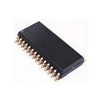
UDA1342TSDB NXP Semiconductors, UDA1342TSDB Datasheet - Page 9

UDA1342TSDB
Manufacturer Part Number
UDA1342TSDB
Description
Audio CODECs AUDIO CODEC MINIDISC
Manufacturer
NXP Semiconductors
Datasheet
1.UDA1342TSN1512.pdf
(45 pages)
Specifications of UDA1342TSDB
Number Of Adc Inputs
4
Number Of Dac Outputs
2
Conversion Rate
110 KSPs
Interface Type
Serial (I2C), L3
Resolution
24 bit
Operating Supply Voltage
2.7 V to 3.6 V
Maximum Operating Temperature
+ 85 C
Mounting Style
SMD/SMT
Package / Case
SSOP-28
Minimum Operating Temperature
- 40 C
Number Of Channels
6
Snr
100 dB
Supply Current
20 mA
Lead Free Status / RoHS Status
Lead free / RoHS Compliant
Other names
UDA1342TS/N1,512
NXP Semiconductors
2000 Jul 31
8.2.2
Since the UDA1342TS is equipped with two stereo ADCs,
these two pairs of stereo ADCs can be used to convert a
single stereo signal to a signal with a higher performance
by using the ADCs in the double differential mode.
This mode and the input signals, being channel 1 or 2 as
input to the double differential configuration, can be
selected via the L3-bus/I
8.3
The decimation from 64f
The first stage realizes a
decimation factor of 8. The second stage consists of three
half-band filters, each decimating by a factor of 2. The filter
characteristics are shown in Table 2.
Table 2 Decimation filter characteristics
8.4
The two stereo ADC outputs are mixed with gain
coefficients from +24 to −63.5 dB to be set via the
microcontroller interface.
In front of the mixer there is a DC filter. In order to prevent
clipping, it is needed to filter out the DC component before
mixing or amplifying the signals.
The mixing function can be enabled via the microcontroller
interface.
8.5
The digital interpolation filter interpolates from 1f
by means of a cascade of FIR filters. The filter
characteristics are shown in Table 3.
Table 3 Interpolation filter characteristics
Audio CODEC
Pass-band ripple
Pass-band droop
Stop band
Dynamic range
Pass-band ripple
Stop band
Dynamic range
ITEM
ITEM
Decimation filter (ADC)
Digital mixer (ADC)
Interpolation filter (DAC)
D
OUBLE DIFFERENTIAL MODE
CONDITION
CONDITION
0 to 0.45f
0 to 0.45f
0 to 0.45f
0 to 0.45f
s
2
to 1f
>0.55f
>0.55f
C-bus interface.
⎛
⎝
0.45f
---------- -
sin
x
s
x
is performed in two stages.
⎞
⎠
s
s
s
4
s
s
s
s
characteristic with a
VALUE (dB)
VALUE (dB)
±0.025
±0.01
>135
>135
−0.2
−70
−60
s
to 64f
s
9
8.6
Muting the DAC will result in a cosine roll-off soft mute,
using 32 × 32 = 1024 samples in the normal mode: this
results in 24 ms at f
is illustrated in Fig.4.
This cosine roll-off functions are implemented in the DAC
data path before the digital mixer and before the master
mute (see Fig.5).
In the L3-bus and I
mute can be overruled always by pin QMUTE. This quick
mute uses the same cosine roll-off, but now for only
32 samples: this is 750 μs at f
8.7
The ADC output signal and the digital interface input signal
can be mixed without an external DSP (see Fig.5).
This mixer can be controlled via the microcontroller
interface.
In order to prevent clipping when mixing two 0 dB signals,
the signals are attenuated digitally by −6 dB before mixing.
After mixing the signal is gained by 6 dB after the master
volume. This way clipping at the digital mixer is prevented.
After the 6 dB gain, the signals can clip again, but this
clipping can be removed by decreasing the master
volume.
handbook, halfpage
factor
mute
Fig.4 Mute as a function of raised cosine roll-off.
0.8
0.6
0.4
0.2
Mute
Digital mixer (DAC)
1
0
0
5
2
s
C-bus mode, the setting of the master
= 44.1 kHz. The cosine roll-off curve
10
s
= 44.1 kHz.
15
UDA1342TS
Product specification
20
t (ms)
MGU119
25


