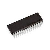
TFA9810T NXP Semiconductors, TFA9810T Datasheet - Page 18

TFA9810T
Manufacturer Part Number
TFA9810T
Description
Audio Amplifiers 2X15W BTL POWER COMPARATOR
Manufacturer
NXP Semiconductors
Datasheet
1.TFA9810TN1112.pdf
(29 pages)
Specifications of TFA9810T
Product
Class-D
Output Power
15 W
Available Set Gain
19.7 dB
Thd Plus Noise
0.04 %
Operating Supply Voltage
12 V
Maximum Power Dissipation
2500 mW
Maximum Operating Temperature
+ 85 C
Mounting Style
SMD/SMT
Audio Load Resistance
8 Ohms
Input Bias Current (max)
1 uA
Input Signal Type
Differential
Minimum Operating Temperature
- 40 C
Output Signal Type
Differential
Supply Type
Single
Supply Voltage (max)
20 V
Supply Voltage (min)
8 V
Output Type
2-Channel Stereo
Package / Case
SOIC-32
Operational Class
Class-D
Audio Amplifier Output Configuration
2-Channel Stereo
Output Power (typ)
15x2@8OhmW
Audio Amplifier Function
Speaker
Total Harmonic Distortion
0.04@8Ohm@1W%
Single Supply Voltage (typ)
12V
Dual Supply Voltage (typ)
Not RequiredV
Power Supply Requirement
Single
Power Dissipation
2.5W
Rail/rail I/o Type
No
Single Supply Voltage (min)
8V
Single Supply Voltage (max)
20V
Dual Supply Voltage (min)
Not RequiredV
Dual Supply Voltage (max)
Not RequiredV
Operating Temp Range
-40C to 85C
Operating Temperature Classification
Industrial
Mounting
Surface Mount
Pin Count
32
Package Type
SO
Lead Free Status / RoHS Status
Lead free / RoHS Compliant
Other names
TFA9810T/N1,112
Available stocks
Company
Part Number
Manufacturer
Quantity
Price
Part Number:
TFA9810T
Manufacturer:
NXP/恩智浦
Quantity:
20 000
Part Number:
TFA9810T/N1
Manufacturer:
NXP/恩智浦
Quantity:
20 000
NXP Semiconductors
Table 11.
T
[1]
13. Quality specification
14. Application information
TFA9810_3
Product data sheet
Symbol
S/N
SVRR
amb
cs
Minimum value determined by R5, R10, R17, R22 equalling +1 % and R7, R14, R18, R20 equalling 1 %.
= 25 C; V
AC characteristics measured in typical application
Parameter
signal-to-noise ratio
supply voltage ripple
rejection
channel separation
P
14.1 Output power estimation
= 12 V; R
In accordance with SNW-FQ-611-E, ‘if this type is used as an audio amplifier’. The
number of the quality specification can be found in the Quality Reference Handbook. The
handbook can be ordered using the code 9398 510 63011.
For BTL configuration the output power just before clipping can be estimated using
Equation
Where,
The output power at 10 % THD can be estimated by using
Figure 26
THD = 10 % as a function of the BLT supply voltage for different load impedances.
P
L
•
•
•
•
•
o
BTL : P
10 %
= 8
V
R
R
R
P
P
o0.5 %
L
DSon
s
= supply voltage (V
= series resistance [ ]
= load resistance [ ]
=
f
1:
osc
o
1.25 P
and
= drain-source on-state resistance [ ]
0.5 %
= output power at the THD level of 0.5 % [W]
Conditions
V
V
P
= 550 kHz;
o
ripple
o
= 10 V (RMS); gain 20 dB
= 1 W; f
Figure 27
=
= 2 V
o
-------------------------------------------------------------------------------- -
0.5 %
----------------------------------------------------- -
R
Rev. 03 — 20 February 2008
i
L
(p-p)
= 1 kHz
Figure 33
+
below show the estimated output power at THD = 0.5 % and
; f
2
DDPx
i
= 1 kHz
R
R
2
L
DSon
unless otherwise specified.
V
R
SSPx
L
+
…continued
R
) [V]
s
V
[1]
P
Min
-
34
55
2
Equation
Typ
96
45
70
Audio amplifier 2 x 12 W
2:
Max
-
-
-
© NXP B.V. 2008. All rights reserved.
TFA9810
Unit
dB
dB
dB
18 of 29
(1)
(2)


