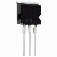
STB200NF04-1 STMicroelectronics, STB200NF04-1 Datasheet

STB200NF04-1
Specifications of STB200NF04-1
Available stocks
Related parts for STB200NF04-1
STB200NF04-1 Summary of contents
Page 1
... APPLICATIONS HIGH CURRENT, HIGH SWITCHING SPEED AUTOMOTIVE Table 2: Order Codes SALES TYPE STB200NF04T4 STB200NF04-1 STP200NF04 October 2004 STB200NF04 - STB200NF04-1 Figure 1: Package 120 A 310 W 120 A 310 W 120 A 310 W Figure 2: Internal Schematic Diagram ...
Page 2
... STP200NF04 - STB200NF04 - STB200NF04-1 Table 3: Absolute Maximum ratings Symbol V Drain-source Voltage ( Drain-gate Voltage (R DGR V Gate- source Voltage GS I (#) Drain Current (continuos (#) Drain Current (continuos Drain Current (pulsed Total Dissipation at T TOT Derating Factor dv/dt (1) Peak Diode Recovery voltage slope E (2) Single Pulse Avalanche Energy ...
Page 3
... Source-drain Current (pulsed) SDM V (1) Forward On Voltage SD t Reverse Recovery Time rr Q Reverse Recovery Charge rr Reverse Recovery Current I RRM (1) Pulsed: Pulse duration = 300 µs, duty cycle 1.5 %. (2) Pulse width limited by safe operating area. STP200NF04 - STB200NF04 - STB200NF04-1 Test Conditions 25V MHz Test Conditions ...
Page 4
... STP200NF04 - STB200NF04 - STB200NF04-1 Figure 3: Safe Operating Area Figure 4: Output Characteristics Figure 5: Transconductance 4/15 Figure 6: Thermal Impedance Figure 7: Transfer Characteristics Figure 8: Static Drain-source On Resistance ...
Page 5
... Figure 9: Gate Charge vs Gate-source Voltage Figure 10: Normalized Gate Thereshold Volt- age vs Temperature Figure 11: Dource-Drain Diode Forward Char- acteristics STP200NF04 - STB200NF04 - STB200NF04-1 Figure 12: Capacitance Variations Figure 13: Normalized On Resistance vs Tem- perature Figure 14: Normalized Breakdown Voltage vs Temperature 5/15 ...
Page 6
... STP200NF04 - STB200NF04 - STB200NF04-1 Figure 15: Thermal Resistance Rthj-a vs PCB Copper Area 6/15 Figure 16: Max Power Dissipation vs PCB Cop- per Area ...
Page 7
... Allowable Current in Avalanche the Average Power Dissipation in Avalanche (Single Pulse) D(AVE the Time in Avalanche AV To derate above 25 °C, at fixed I Where the value coming from Normalized Thermal Response at fixed pulse width equal STP200NF04 - STB200NF04 - STB200NF04 the following equation must be applied jmax CASE * Z ) DSS th ...
Page 8
... STP200NF04 - STB200NF04 - STB200NF04-1 Table 9: 6th Order RC Network Parameter Node CTHERM1 CTHERM2 CTHERM3 CTHERM4 CTHERM5 CTHERM6 RTHERM1 RTHERM2 RTHERM3 RTHERM4 RTHERM5 RTHERM6 Figure 18: Schematic of 6th Order RC Network 8/15 SPICE THERMAL MODEL Value 1.4958E-3 3.5074E-2 5.939E-2 9.7411E-2 8.8596E-2 8.2755E-1 0.0384 0.0624 0.072 0.0912 ...
Page 9
... Figure 19: Unclamped Inductive Load Test Cir- cuit Figure 20: Switching Times Test Circuit For Resistive Load Figure 21: Test Circuit For Inductive Load Switching and Diode Recovery Times STP200NF04 - STB200NF04 - STB200NF04-1 Figure 22: Unclamped Inductive Wafeform Figure 23: Gate Charge Test Circuit 9/15 ...
Page 10
... STP200NF04 - STB200NF04 - STB200NF04-1 DIM. MIN. A 4.40 b 0.61 b1 1.15 c 0.49 D 15. 2.40 e1 4.95 F 1.23 H1 6. 3.50 L20 L30 øP 3.75 Q 2.65 10/15 TO-220 MECHANICAL DATA mm. TYP MAX. MIN. 4.60 0.173 0.88 0.024 1.70 0.045 0.70 0.019 15.75 0.60 10.40 0.393 2.70 ...
Page 11
... C 0.45 C2 1. 8 1.27 L3 1.4 M 2.4 R 0.4 V2 0º STP200NF04 - STB200NF04 - STB200NF04-1 inch MAX. MIN. TYP. 4.6 0.173 2.69 0.098 0.23 0.001 0.93 0.027 1.7 0.044 0.6 0.017 1.36 0.048 9.35 0.352 0.315 10.4 0.393 0.334 5.28 0.192 15 ...
Page 12
... STP200NF04 - STB200NF04 - STB200NF04-1 DIM. MIN. A 4.40 A1 2.40 b 0.61 b1 1.14 c 0.49 c2 1.23 D 8.95 e 2. 3.50 L2 1.27 12/15 2 TO-262 (I PAK) MECHANICAL DATA mm. TYP MAX. MIN. 4.60 0.173 2.72 0.094 0.88 0.024 1.70 0.044 0.70 0.019 1.32 0.048 9.35 0.352 2.70 0.094 5.15 ...
Page 13
... P1 11.9 12.1 0.468 0.476 P2 1.9 2.1 0.075 0.082 R 50 1.574 T 0.25 0.35 0.0098 0.0137 W 23.7 24.3 0.933 0.956 * on sales type STP200NF04 - STB200NF04 - STB200NF04-1 TUBE SHIPMENT (no suffix)* REEL MECHANICAL DATA mm DIM. MIN. MAX. A 330 B 1.5 C 12.8 13.2 D 20.2 G 24.4 26.4 N ...
Page 14
... STP200NF04 - STB200NF04 - STB200NF04-1 Table 10: Revision History Date Revision 28-Sep-2004 2 11-Oct-2004 3 14/15 Description of Changes New Stylesheet. No Content Change Final datasheet ...
Page 15
... Australia - Belgium - Brazil - Canada - China - Czech Republic - Finland - France - Germany - Hong Kong - India - Israel - Italy - Japan - Malaysia - Malta - Morocco - Singapore - Spain - Sweden - Switzerland - United Kingdom - United States of America STP200NF04 - STB200NF04 - STB200NF04-1 All other names are the property of their respective owners © 2004 STMicroelectronics - All Rights Reserved ...


